
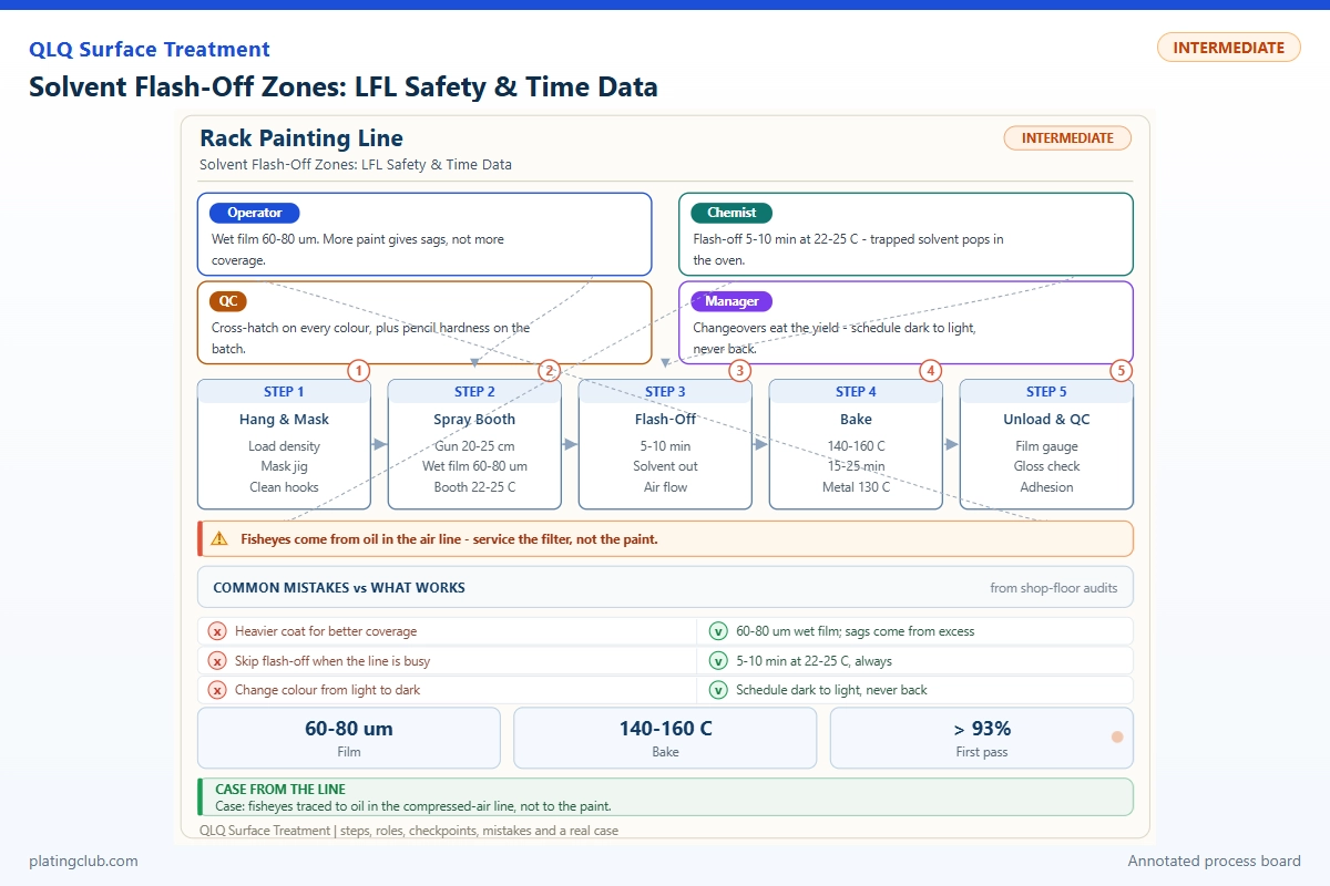
Solvent Flash-Off Zones: LFL Safety & Time Data
What a Junior Painting Technician Must Control
A flash-off zone is the ventilated interval between application and the next coating or heating stage. Solvent leaves the wet film while the coating levels. Too little time can carry excessive solvent into the oven; excessive airflow or unsuitable solvent can dry the surface before the film levels. Neither a smooth finish nor a dry-looking surface proves that the surrounding atmosphere is safe.
For zinc-alloy sliders and bag hardware, control three linked items: the approved coating mixture, actual residence time, and verified ventilation. QLQ's process notes place leveling between spraying and baking and identify fast evaporation, high viscosity, moisture and rapid heating as defect contributors. They do not specify a universal flash-off duration or an approved LFL alarm schedule.
Evidence boundary: the recipe below is knowledge-base-backed; time calculations are illustrative. No measured flash-off comparison dataset was supplied or found. The experimental table therefore identifies pending measurements rather than inventing hardness, film thickness or salt-spray results. Safety thresholds shown as examples are not commissioning instructions. Current supplier documents, local requirements and a competent engineer must approve the actual operating envelope.
Weigh matched componentsMeasure actual time
Zone length divided by speedProve extraction
Fan noise is not airflow proof
LFL Is Not the Same as Solvent Percentage in Paint
The lower flammable limit, LFL, is the lowest fuel-vapor concentration in air that can propagate flame under specified conditions. LEL is commonly used for the same lower-limit concept. A detector reading of 10% LEL means one-tenth of its relevant lower limit, not 10% solvent vapor by volume. Calibration gas, solvent response factors and sensor location all affect what that reading means.
Illustrative arithmetic: if a verified solvent SDS gives an LFL of 1.0% by volume, 10% of that LFL corresponds to 0.10% vapor, or 1,000 ppm. This is a calculation, not the LFL of QLQ thinner. Its exact composition, mixture LFL, flash point and occupational exposure limits are not available in the inspected notes. Obtain its current SDS before evaluating a line.
Use independent exposure controls. A concentration below a flammability alarm can still exceed a health limit. Odor is not a detector, and respiratory protection does not replace extraction. Exhaust from low points, cavities and crowded racks deserves attention because a single sensor cannot prove every location safe.
On an alarm or ventilation fault, follow the written emergency sequence: stop further coating and solvent admission, keep engineered extraction operating when the approved sequence requires it, exclude ignition sources and notify the responsible supervisor. Conveyor and heater responses must follow the validated interlock logic; casually stopping the conveyor can leave wet parts concentrated at a hot entrance. Do not repeatedly reset a trip.
Working Data & Formula Notes: A Complete Application Mix
The QLQ chemical reference identifies normal thinner item M002338 and gives paint:hardener:thinner = 3:1:3–4 by weight for slider painting. This is a complete three-component application mixture, not a disclosure of the paint's resin chemistry or thinner's solvent composition. Confirm the matched paint and hardener, current technical data sheet, mixing order, induction time and pot life before use.
| Component | Range | Typical | Function | Replenishment |
|---|---|---|---|---|
| Matched slider paint | 3 weight parts; 37.50–42.86% of final mix | 3.000 kg; 40.00% | Supplies binder, pigment and the specified coating package | Prepare a fresh weighed batch; do not add paint alone to an aging mixed pot. |
| Matched hardener | 1 weight part; 12.50–14.29% | 1.000 kg; 13.33% | Provides the matched curing component | Maintain the 3:1 paint-to-hardener ratio; never add extra hardener to compensate for poor curing. |
| Normal thinner, reference item M002338 | 3–4 weight parts; 42.86–50.00% | 3.500 kg; 46.67% | Adjusts application viscosity and contributes volatile loading | Only measured additions allowed by the current supplier instructions; record cumulative addition. |
| Total application mixture | 7–8 weight parts; 100% | 7.500 kg; 100% | Complete ready-to-apply reference batch | Label preparation time, component lots and discard deadline; replace expired material. |
The range endpoints are coupled: 3:1:3 gives 42.86%, 14.29% and 42.86%; 3:1:4 gives 37.50%, 12.50% and 50.00%. Do not choose independent endpoints and expect a valid recipe. The midpoint is a calculation, not a supplier-certified optimum. Never convert these weight ratios directly into volume ratios.
At the midpoint, added thinner alone is 46.67% of the wet mix. Paint and hardener may contain additional solvent, so 46.67% is not the total VOC fraction. Extract volatile-content and density information from the actual documents. Do not substitute generic xylene or another thinner merely because its viscosity adjustment seems similar.
Flash-Off Time and Vapor Loading: Keep the Units Visible
For a continuous conveyor, residence time in minutes is effective ventilated length in metres divided by speed in metres per minute. A 6.0 m zone at 1.0 m/min gives 6.0 minutes; at 0.75 m/min it gives 8.0 minutes; at 0.60 m/min it gives 10.0 minutes. These are geometrical examples, not validated flash-off recommendations. Count only the portion providing the intended ventilation and environment.
Record stops and slowdowns separately. A rack sitting beside the oven entrance does not experience the same temperature and airflow as one traveling normally. Start timing after the last relevant application pass, not after the first part entered the booth. For manually moved batches, use entry and exit timestamps and identify the oldest and newest coated parts.
For engineering screening, estimate released solvent mass rate as coating consumption multiplied by total volatile mass fraction and the fraction released in this zone. An assumed 12 kg/h of wet coating, 0.60 volatile fraction and 0.50 zone-release fraction gives 3.6 kg/h. Each assumption must be replaced with actual process information before design decisions.
Mass rate divided by measured exhaust volume gives an ideal mixed concentration estimate: 3.6 kg/h divided by 6,000 m3/h equals 0.60 g/m3. It does not establish local peak concentration, account for incomplete mixing or justify reducing extraction. Converting this mass concentration to %LFL requires solvent composition and temperature-dependent information. Only the engineer may use a validated model to establish capacity.
Experimental Comparison Sheet: Collect Evidence Before Release
Run trials only inside an already approved safe operating envelope. Compare identical prepared substrates, coating lots, application settings and cure schedules. Use at least three replicate coupons per condition, placed beside representative parts. Record individual readings and variation; one attractive coupon cannot validate a production batch.
| Coupon / batch | Test condition | Calculated flash-off | Measured dry-film thickness | Hardness / adhesion | Salt-spray result | Disposition |
|---|---|---|---|---|---|---|
| A1–A3 / reference | Illustrative 6.0 m zone; 1.00 m/min; approved coating and cure unchanged | 6.0 min | Pending; record mean, minimum and maximum in micrometres | Pending; same method and conditioning for all sets | Pending; only if required by product specification | Not released |
| B1–B3 / comparison | Same setup; 0.75 m/min; test only with engineer-approved exposure and cure controls | 8.0 min | Pending; use substrate-compatible calibrated method | Pending; record hardness rating and adhesion classification | Pending; record exposure hours and failure criterion | Not released |
| C1–C3 / comparison | Same setup; 0.60 m/min; maintain identical approved oven thermal history | 10.0 min | Pending; examine recesses separately | Pending; include cure-conditioning interval | Pending; retain photographs and coupon IDs | Not released |
If one conveyor also determines oven dwell, changing speed changes two variables. Isolate flash-off with an approved separate trial arrangement or log actual part-temperature profiles and treat the experiment as a combined-process comparison. Select current agreed methods for film thickness, pencil hardness, adhesion and salt spray; record method edition, substrate, preparation, conditioning, exposure and acceptance criteria. Salt-spray hours are not a prediction of service life.
The QLQ general painting note lists 15–30 micrometres as a coating-thickness reference. Use it as background, not automatic trial acceptance. Film specifications depend on the coating, geometry and customer requirement. Release requires measured results and engineering approval; blanks must never become inferred “passes.”
Trend Bands: Distinguish Process Drift from Safety Trips
The following numerical bands illustrate how to build a shift chart. They are proposed training values, not verified site limits or universal legal thresholds. Replace them with signed site settings before production. An unsafe condition requires action even when the other parameters remain normal.
| Parameter | Normal fluctuation band | Danger / escalation threshold | Required response |
|---|---|---|---|
| Solvent detector | Example target below 10% LEL, using approved correction | Example warning at 10%; trip at 20%; actual setpoints require hazard review | Execute approved sequence; do not treat a higher reading as acceptable spare capacity. |
| Verified exhaust flow | At or above validated minimum; trend within qualified operating range | Below validated minimum, failed airflow proof or detector fault | Inhibit solvent admission through the validated interlock. |
| Flash-off time | Example qualified target 8 minutes, band 7–9 | Outside qualified minimum or maximum | Hold affected parts; investigate timing and coating state. |
| Zone air temperature | Example qualified band 20–25°C | Outside supplier-approved range; example escalation below 18 or above 30°C | Escalate; no unauthorized heaters or solvent substitutions. |
| Coating viscosity | Example 20–24 seconds with specified cup at 23°C | Outside qualified limits; example below 18 or above 26 seconds | Check temperature, mixture age and approved thinner addition. |
| Dry-film thickness | Example product target 20–25 micrometres | Outside signed drawing limits; example below 15 or above 30 micrometres | Quarantine and review deposition; do not conceal excess build with extra bake time. |
| Mixed-paint age | Within documented usable interval at actual temperature | At supplier pot-life deadline or abnormal reaction | Replace material; thinning does not restart pot life. |
Engineer Notes: Seven Actions That Prevent Guesswork
- Measure conveyor speed with a timed marked distance. Compare it with the drive display and write the calculated residence time on the batch sheet.
- Verify airflow using the approved instrument and reference locations. Check blocked filters, closed dampers and disconnected pressure lines before blaming the sensor.
- Perform detector bump checks and calibration at the documented intervals with trained personnel. Record gas identity, expiry and solvent-response settings.
- Weigh all components with a checked scale. Attach lot labels and preparation time to the mixed container; keep lids closed when compatible with the approved supply arrangement.
- Place coupons near difficult recesses and heavily loaded rack positions. Record wet-film observations without touching or damaging production surfaces.
- Inspect grounding, bonding and approved electrical equipment during the authorized checklist. Never install an ordinary fan, lamp or portable heater in a classified solvent area.
- After any trip, identify the affected time window and segregate its parts. Restart only through the authorized procedure after the cause and control functions are verified.
Shift Checks
| Shift stage | Check item | Frequency | Acceptance standard | Record |
|---|---|---|---|---|
| Before | SDS, mixture identity and pot-life instructions | Each start and material change | Current documents; matched components; approved recipe | Document revision and component lot IDs |
| Before | Extraction, detector readiness and safety permissives | Each start; tests per approved schedule | Validated airflow; detector healthy; no bypass | Flow, sensor status and operator signature |
| During | Vapor concentration and ventilation proof | Continuous monitoring; logged per site schedule | Below approved warning level; airflow proven | Trend and alarm history |
| During | Speed, temperature, viscosity and mixture age | Example hourly; also after stops or changes | Within signed process bands | Time-stamped readings and corrections |
| During | Representative film and coupon identification | First batch and approved sampling interval | Product-specific film and appearance criteria | Coupon IDs, readings and disposition |
| After | Residual solvent, waste and shutdown sequence | Every shutdown | Approved ventilation run-on complete; containers closed and waste secured | Shutdown time and responsible person |
| After | Exceptions and handover | Each handover | No unassigned alarm investigation or unmarked hold batch | Hold list, actions and next owner |
Two Troubleshooting Scenarios
Scenario 1: recessed bag hardware develops bubbles. This is a training scenario, not a reported customer case. First confirm pretreatment dryness, film build and actual cure history. Compare approved flash-off conditions with labeled coupons. QLQ's defect note associates bubbling with retained moisture and rapid baking; bubbles alone cannot identify retained solvent. Change one qualified variable at a time and retain the rejected parts.
Scenario 2: the vapor trend rises after a rack-loading change. Treat this as a safety investigation, not a cosmetic adjustment. Check wet coating consumption, loading density, exhaust proof and sensor response. A slower conveyor may extend residence but concentrate wet parts or alter oven exposure. Reduce or stop solvent admission through the approved sequence and let engineering evaluate the new loading condition before restart.
FAQ: Technician-to-AI Questions
These are example technician prompts, not quotations from verified customer correspondence.
“AI, the parts look dry after three minutes. Can I send them straight into the oven?”
Appearance does not establish residual solvent or safe oven loading. Check the signed flash-off minimum, actual zone conditions and approved coating instructions. Hold the batch if the required interval was missed. Do not override the oven permissive because a surface looks dry.
“AI, my detector says 12% LEL. Is that only 12 ppm, and can I keep painting?”
No. %LEL expresses a fraction of a lower explosive limit, not ppm. Its interpretation requires calibration and solvent-response information. Follow the site's alarm schedule immediately; the training example places 12% above its warning point. Notify the supervisor and use the approved response, not an AI decision to continue.
“AI, can I add more thinner to old mixed paint and start the pot-life clock again?”
No. Added thinner can change viscosity and volatile loading but does not reverse curing chemistry or restore expired pot life. Check preparation time and actual material temperature. Replace expired mixture under the approved waste procedure and prepare a correctly weighed fresh batch.
What Would You Like to Solve?
For a process review, send the coating TDS and SDS, component lots, measured zone length, conveyor speed, ventilation readings, detector configuration and labeled defect photographs to [email protected]. Describe the operating problem and the missing measurements. See integrated surface-treatment line, equipment and chemical support for the broader process context. Site safety approval remains the responsibility of the qualified local team.
Knowledge-base provenance: QLQ Obsidian Vault, surface-treatment process notes on painting and painting defects; equipment note on painting and baking equipment; chemical quick-reference table, item M002338. Source identifiers: painting-process note; painting-defect-analysis note; painting-and-baking-equipment note; chemical-quick-reference table. Exact source file paths are retained in the HTML comments below. For safety verification, consult the current OSHA spray-finishing requirements where applicable, the current local fire requirements and actual supplier documents. The external regulatory page could not be retrieved during drafting; no numerical example here is presented as a verified quotation from that regulation.