
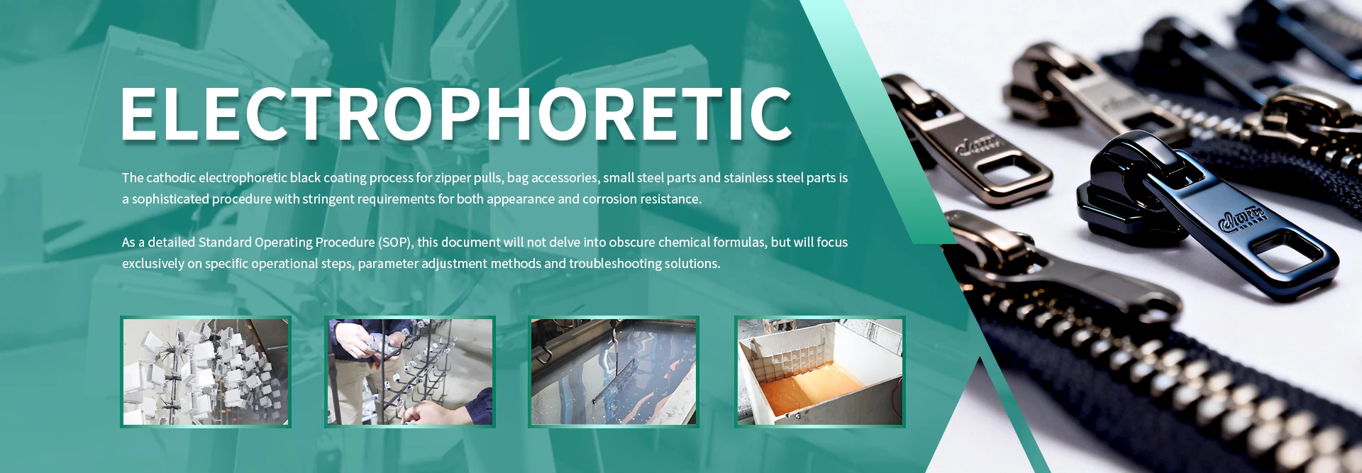
Electrophoretic Coating (E-Coating) — Complete Coverage, Superior Corrosion Resistance
Charged paint particles deposit on every surface — edges, cavities, threads — with 96–200+ h salt spray resistance. The primer of choice for automotive-grade hardware.
The E-Coating Process
Clean → Rinse → E-Coat → UF Rinse → Cure → Cool → QC
1Electrophoresis Principle
Paint particles suspended in water carry an electric charge. Under DC voltage, they migrate toward the oppositely charged workpiece and deposit on the surface. Cathodic e-coat (CED) is the dominant technology — the part is the cathode.
2Cathodic vs Anodic E-Coating
Cathodic (CED): part = negative, attracts positive paint ions → better corrosion resistance (96–200+ h salt spray). Anodic (AED): part = positive, attracts negative paint ions → cheaper, less corrosion resistant (< 72 h). CED is the industry standard for automotive and premium hardware.
3Process Parameters
Voltage ramp-up (0 → target over 15–30 s) prevents film rupture. Temperature control ±1 °C for consistent film build. pH and conductivity monitored hourly. Film thickness 15–25 μm per deposition.
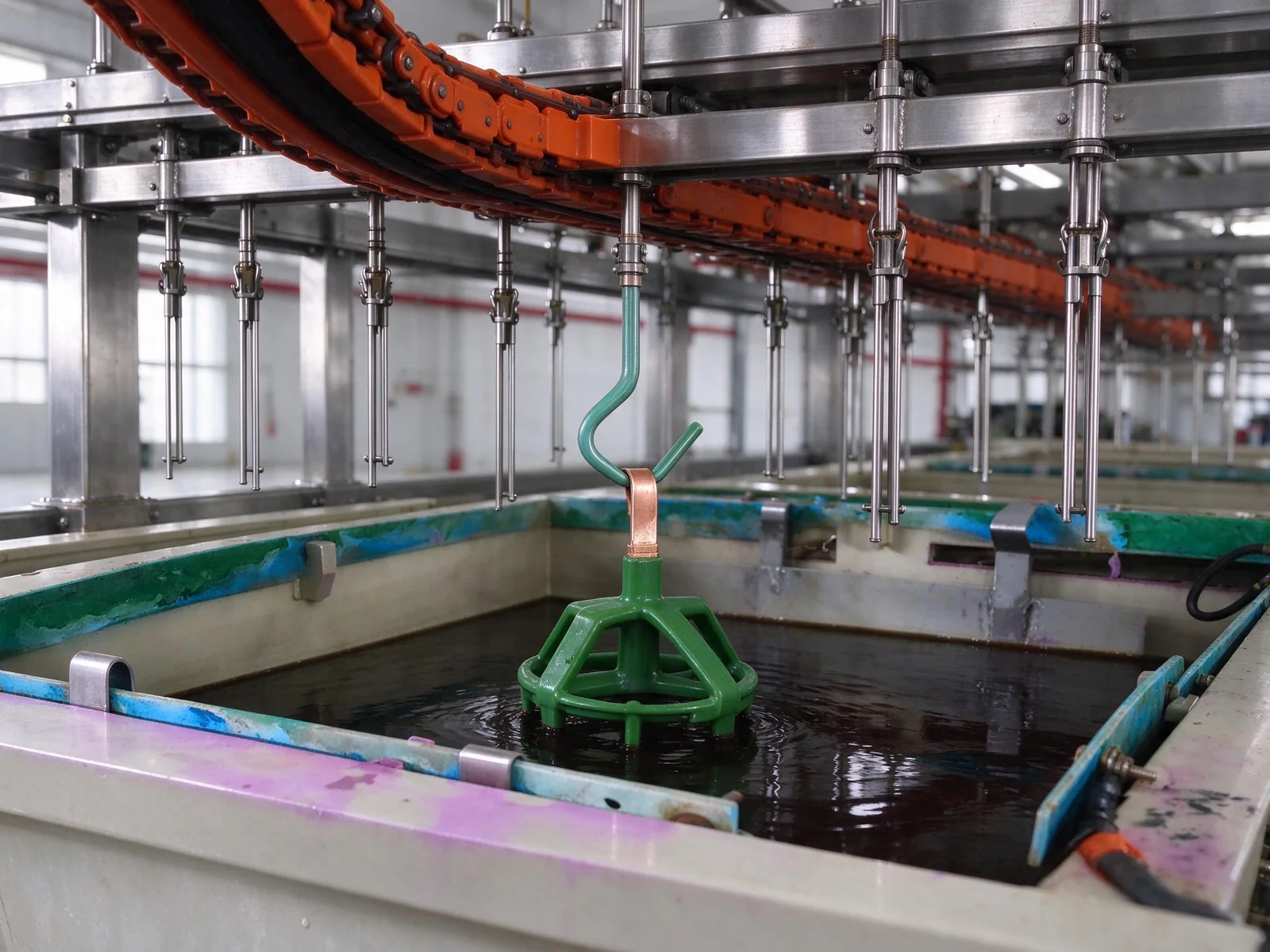 Conceptual illustration based on reference photographs; not test evidence.
4Curing the E-Coat
Cure at 160–180 °C for 20–30 min. The cross-linked film provides excellent hardness, chemical resistance and adhesion. Under-cure = soft film, over-cure = embrittlement and discoloration.
E-Coating Color Options & Performance
Clear, black, grey and custom colors — all with the same full-coverage advantage
| Color | Pigment | Salt Spray | Typical Use | Cost Factor |
|---|---|---|---|---|
| Clear / Transparent | None | 96–120 h | Color protection layer, anti-tarnish | Standard |
| Black | Carbon black | 120–200+ h | Automotive, hardware, fasteners | Standard |
| Grey | TiO₂ + carbon | 120–200+ h | Industrial equipment | Standard + 5% |
| White | TiO₂ | 96–150 h | Decorative hardware | Standard + 10% |
| Red / Blue / Green | Organic pigments | 96–150 h | Branded / fashion hardware | Premium + 15–25% |
| Zinc-rich primer | Zn dust | 500+ h | Marine / heavy corrosion | Premium |
📌 E-Coating Cheat Sheet
FAQ
What metal substrates can be e-coated?
How does e-coat compare to powder coating?
Can we do partial e-coating (selective areas only)?
Why is my e-coat film rough / grainy?
What rectifier voltage curve is best?
Cathodic Epoxy Electrophoresis (e-coat) Bath Reference
These working ranges are the reference values supplied for this article, not a universal formulation specification. Typical values are illustrative midpoints, not validated production setpoints. Confirm all limits with the coating supplier's technical data sheet and the approved line recipe before adjusting the bath.
Working Ranges
| Parameter | Range | Typical | Control method |
|---|---|---|---|
| Solids | 14–18% | 16% | Measure nonvolatile content using the supplier's approved gravimetric method; adjust only with approved replenishment materials. |
| pH | 5.8–6.4 | 6.1 | Use a calibrated pH meter at the specified sample temperature; follow the supplier's correction procedure. |
| Conductivity | 1200–1800 µS/cm | 1500 µS/cm | Use a calibrated conductivity meter with consistent temperature compensation; investigate ionic carryover and follow the approved UF bleed procedure. |
| Voltage | 150–250 V | 200 V | Verify rectifier output and the approved voltage ramp; confirm coating appearance and thickness on representative parts. |
| Time | 120–180 s | 150 s | Check actual energized immersion time against the PLC timer or conveyor speed. |
| Temperature | 28–32°C | 30°C | Check the bath with a verified temperature probe; monitor circulation, heat exchanger and chiller operation. |
| Film build | 18–25 µm | 21.5 µm | Measure cured dry-film thickness with a substrate-appropriate, calibrated gauge at defined inspection locations. |
Bath make-up
Percentages refer to the working bath. Resin and pigment additions require the supplier's concentrate solids and approved pigment-to-binder ratio; the brief does not specify these percentages.
| Component | % | Note |
|---|---|---|
| Epoxy resin dispersion | To be confirmed by supplier | Use the approved cathodic epoxy binder; calculate the addition from concentrate solids and the target working-bath solids. |
| Pigment paste (gray/black) | To be confirmed by supplier | Use a compatible paste at the specified pigment-to-binder ratio; do not interchange grades without approval. |
| Deionized water balance | Balance to 100% | Complete the approved make-up with DI water after accounting for resin and pigment additions. |
| Ultrafiltrate for rinsing | Not applicable to bath make-up | Use in the approved post-e-coat rinse circuit; control rinse recovery and bleed separately from the bath formulation. |
Engineer Notes
- Rising conductivity: Check pretreatment carryover, DI water quality and the measured conductivity trend. Use a controlled ultrafiltrate (UF) bleed with approved DI water replacement when prescribed by the supplier; route the bleed to the authorized wastewater system and recheck bath controls.
- Excessive voltage and pinholes: High voltage can cause roughness and pinholes. Review the voltage ramp and reduce voltage within the approved recipe, then verify film build and appearance before releasing production.
- Temperature and bath stability: Higher temperature can increase film build but also raises the risk of emulsion destabilization. Keep the bath within its supplier-approved temperature window and investigate loss of cooling promptly.
- Rack contact resistance: Inspect rack hooks, contact points and electrical connections for coating buildup or poor contact. Clean and service them under the site's isolation procedure; verify reliable contact before comparing film thickness between racks.
- Cleaning after PIC: The brief does not define PIC; confirm its meaning and the applicable cleaning procedure with the line engineer. Complete the specified post-PIC cleaning and rinsing, and verify that no cleaning residue enters the coating bath.
Bath temperature above 35°C starts resin coagulation — check chiller before every shift.
This is the warning threshold specified in the article brief. Actual coagulation onset depends on the resin formulation; confirm the supplier's maximum operating temperature and alarm settings, and apply any lower approved limit.
Reference basis: geo_articles/enhance_electrophoresis.txt. Supporting process reference: QLQ knowledge-base file 032, Electrophoretic Coating Process (IMA company knowledge-base extract). Its general operating ranges differ from this article's supplied values; the coating supplier's validated recipe takes precedence.
Get a Free Quote Today
Send us your samples or drawings — our engineers reply within 24 hours with pricing and technical advice.
Contact Us