
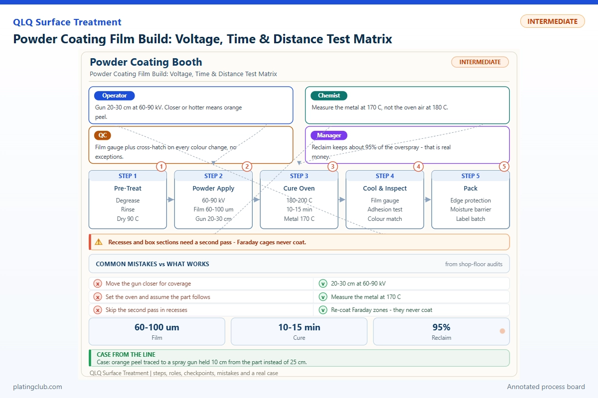
Powder Coating Film Build: Voltage, Time & Distance Test Matrix
Increasing voltage does not guarantee a thicker, more uniform powder coating. Film build depends on powder delivery, charging, part grounding, geometry and exposure time. An intermediate technician should establish a repeatable operating window, not chase the highest thickness reading. Start with clean contacts and stable powder output, then test voltage, spraying time and gun distance independently before checking their interactions.
This guide addresses corona application on metal finishing parts, including zinc-alloy bag hardware. The proposed production trial uses an indoor, solid-color hybrid powder; metallic finishes require their own qualification. Numerical trial settings and control bands below are engineering starting points, not QLQ-certified specifications or customer test results. The powder supplier's technical data sheet, equipment manual and approved drawing take precedence.
Three application factors | Three replicate parts per condition | Five mapped measurement sites | Seven engineer actions | Separate deposition from cure
1. Establish a trustworthy baseline
Select one powder batch, one substrate alloy and one pretreatment route. Use flat witness coupons alongside representative production parts; a flat coupon alone cannot reveal an undercoated buckle recess. Record nozzle, hose length, hanger orientation, reclaim fraction and measured powder output. Keep these fixed throughout the screening experiment.
Check continuity from the actual part through its hook to earth. Gema's OP17 operating instructions specify a maximum contact-to-earth resistance of 1 MOhm and regular hook cleaning. Follow the installed equipment's current manual and site safety procedure. Test with high voltage disabled, using an approved instrument and competent personnel; never defeat grounding or extraction interlocks to obtain a comparison sample.
Define a provisional cured dry-film thickness target of 60–90 micrometers only if the selected powder and customer requirement permit it. Mark center, edge, recess, back and contact-adjacent sites. Use an eddy-current gauge for nonferrous zinc or aluminum and an appropriate magnetic method for steel. Validate curvature effects; use section microscopy where the probe cannot reliably measure a small recess.
Spraying time means total trigger-on exposure for a defined path, not oven dwell. Freeze the number of passes, overlap and spray angle. Profile actual part-metal temperature separately: oven air temperature cannot demonstrate that a heavy casting reached the powder's cure window.
2. Working Data & Formula Notes
The Typical column reproduces the complete orange hybrid formulation in Table 1 of Li and colleagues' powder-coating study. Values are weight percent, also kilograms per 100-kilogram batch. Range entries are proposed formulation-development bounds around that reference, not published tolerances. They must be evaluated by the powder manufacturer, with total composition normalized to 100% and binder stoichiometry preserved.
| Component | Range | Typical | Function | Replenishment |
|---|---|---|---|---|
| Polyester, CRYLCOAT 1701-0 | 37–39% | 38.0% | Primary film-forming binder | Finished powder only |
| Epoxy, DER 663U | 17.9–18.9%, coupled to polyester | 18.4% | Hybrid crosslinking partner | Finished powder only |
| Accelerator, VESTAGON B 68 | 0.15–0.25% | 0.2% | Cure acceleration | No booth dosing |
| Leveling agent, Resiflow PL-200 | 0.6–1.0% | 0.8% | Melt leveling | No booth dosing |
| Benzoin | 0.15–0.30% | 0.2% | Degassing | No booth dosing |
| Barium sulfate, Sparwite W-10 | 28–32% | 30.0% | Extender; solids balance | Finished powder only |
| Red pigment, Irgalite Red D 3773 | 1.4–1.8% | 1.6% | Color contribution | No color correction in hopper |
| Orange pigment, Irgalite Orange L 2970 | 3.8–4.6% | 4.2% | Color contribution | No color correction in hopper |
| Titanium dioxide, CR880 | 6.0–7.2% | 6.6% | Opacity | Finished powder only |
| Total | Normalize every variant | 100.0% | Complete batch | Approved virgin powder |
A powder hopper is not an electroplating bath. Do not add loose benzoin, resin, pigment or solvent to correct a production defect. Replenish with approved finished powder and control reclaim by mass. Excess accelerator can shorten flow time; changing pigment or extender loading can alter opacity, melt behavior and charging. Any formulation change invalidates the existing application qualification.
For planning, theoretical deposited mass equals coated area multiplied by cured thickness and coating density. At 1 square meter, 75 micrometers and an assumed density of 1.5 grams per cubic centimeter, deposited mass is 112.5 grams. Divide by measured first-pass transfer efficiency to estimate required feed; density is an assumption until verified for the actual powder.
3. Build the voltage, time and distance matrix
Use a full two-level factorial to expose interactions: eight corner conditions plus a center reference repeated at the beginning, middle and end. Each condition receives three independently coated parts and corresponding witness coupons. Randomize corner-run order. The center references detect drift from hopper level, injector wear or operator changes.
| Condition | Voltage magnitude | Trigger-on time | Distance | Test condition |
|---|---|---|---|---|
| M1 | 40 kV | 6 seconds | 200 mm | Three parts; fixed path and powder batch |
| M2 | 70 kV | 6 seconds | 200 mm | Same baseline controls |
| M3 | 40 kV | 10 seconds | 200 mm | Same baseline controls |
| M4 | 70 kV | 10 seconds | 200 mm | Same baseline controls |
| M5 | 40 kV | 6 seconds | 300 mm | Same baseline controls |
| M6 | 70 kV | 6 seconds | 300 mm | Same baseline controls |
| M7 | 40 kV | 10 seconds | 300 mm | Same baseline controls |
| M8 | 70 kV | 10 seconds | 300 mm | Same baseline controls |
| Center, repeated three times | 55 kV | 8 seconds | 250 mm | Start, middle and end references |
Begin with a 20-microampere current limit and measured delivery near 80 grams per minute as provisional controls, subject to equipment suitability. Log actual displayed current and voltage under load. Current limiting can reduce actual voltage, making nominally different settings electrically similar. If this occurs, document it before interpreting the matrix.
Measure cured thickness at every marked site and retain individual readings. Compare minimum recess thickness, maximum edge thickness, site-to-site spread, deposited mass and visible defects. Calculate factor effects as the average response at the high level minus the average at the low level. Do not select the thickest mean: choose the lowest material consumption that consistently satisfies all local requirements.
4. Published experimental comparison and production validation
The following external specimen comparison supplies real reference data, not invented plant results. Film thickness was a controlled study condition, not evidence that one method deposited more powder.
| Specimen | Preparation | Powder D50 | Film thickness condition | Test condition | Salt spray / hardness |
|---|---|---|---|---|---|
| G1 | Conventional extrusion | 37.76 micrometers | 75 ± 2.5 micrometers | Aluminum; −35 kV; three panels | Not reported in this comparison |
| E1 | Ultrafine blending, pressing, regrinding | 38.75 micrometers | 75 ± 2.5 micrometers | Aluminum; −35 kV; three panels | Not reported in this comparison |
| H1 | Regular-powder blending | 37.23 micrometers | 75 ± 2.5 micrometers | Aluminum; −35 kV; three panels | Not reported in this comparison |
Source: published experimental study. Its aluminum specimens do not establish corrosion performance on zinc castings. For your matrix, add measured thickness, pencil hardness, adhesion and corrosion results to the batch record; leave unavailable results explicitly pending.
Confirm the selected settings over three production batches. Use the same conditioning period before hardness and adhesion checks. Define the pencil endpoint, adhesion method and acceptance criteria in the quality plan. For neutral salt spray, specify the agreed method, exposure duration, scribe geometry, edge sealing and corrosion-rating criterion before testing. Salt-spray hours are not service-life predictions, and thicker films cannot compensate for unsuitable pretreatment.
5. Normal fluctuation bands versus danger thresholds
These are proposed control-plan limits for the solid-color trial, not universal physical danger points. Replace them with qualified settings after validation. A trend crossing a warning band triggers investigation; a product limit breach triggers segregation.
| Parameter | Normal fluctuation band | Danger / intervention threshold | Action |
|---|---|---|---|
| Voltage setting | Qualified nominal ± 5 kV | Departure >10 kV or unstable actual output | Restore recipe; inspect electrode and controller |
| Current limit | 15–25 microamperes around trial baseline | >30 microamperes with recess starvation or cratering | Reduce charge; compare recess coverage |
| Gun distance | Qualified nominal ± 20 mm | Deviation >50 mm | Reset mechanical stop or robot path |
| Trigger-on exposure | Qualified nominal ± 5% | Deviation >10% | Check timing, speed and pass overlap |
| Measured powder output | Qualified nominal ± 10% | Deviation >15% or visible surging | Inspect feed system before changing voltage |
| Part-to-earth resistance | Site target ≤0.1 MOhm | ≥1 MOhm or intermittent contact | Stop spraying; restore and verify grounding |
| Cured thickness | Provisional 60–90 micrometers at required sites | Any required site outside approved limits | Hold affected output; map defect location |
| Booth relative humidity | 40–60% | <35% or >65%, proposed warning limits | Check room conditions and powder handling |
The humidity band and charging, feed and penetration mechanisms are supported by PPG's troubleshooting guide. The tighter warning limits are proposed site controls. For metallic/effect finishes, AkzoNobel's application guidance instead gives starting ranges of 50–80 kV, 8–20 microamperes and 250–400 mm. Do not transfer the solid-color matrix unchanged.
6. Two reference cases that prevent wrong conclusions
Case A: Similar particle size, different manufacturing history
The published G1/E1/H1 comparison above holds film build constant while changing powder preparation. Its practical lesson is to retain powder batch and processing history when diagnosing finish changes. If a replacement batch behaves differently at unchanged gun settings, ask for powder-quality evidence before modifying the entire line recipe. This is an external research case, not a QLQ customer installation.
Case B: Opacity improvement without excessive film build
Patent CN1506423A reports a white epoxy/polyester development using pigment surface treatment and improved dispersion, with claimed thickness reduction from 70–80 to 45–50 micrometers while maintaining hiding and other properties. The operating lesson is to distinguish poor opacity from poor deposition. This patent claim is not independent certification or permission to reduce your specified minimum thickness; qualify a suitable powder with the supplier first.
7. Engineer Notes
- Strip hook contact points before the trial, test the loaded part-to-earth path, and tag the verified rack. A clean rack frame does not prove that every part is grounded.
- Calibrate powder output by collecting a timed discharge into an approved grounded receiver under the manufacturer's safe procedure. Repeat three collections; investigate inconsistent mass before spraying specimens.
- Set nozzle distance with a mechanical fixture, checked while spraying is disabled. Photograph the reference orientation so another operator can reproduce the geometry.
- Spray recesses before broad faces. If the recess remains thin while edges grow, reduce current and excessive conveying air rather than extending every pass. Record the changed path as a separate recipe.
- Attach temperature probes to representative thin and heavy sections. Start cure holding time when the relevant metal location reaches the required temperature, not when the rack enters the oven.
- Validate gauge readings on matching uncoated substrate and certified shims. Mark measurement locations permanently on the inspection sketch; do not substitute accessible flat faces for difficult recesses.
- Retain one labeled witness coupon from every confirmation batch. Release settings only after reviewing local thickness, appearance, cure, adhesion and any contractually required corrosion test.
8. Shift Checks
| Shift stage | Check item | Frequency | Acceptance criterion | Record |
|---|---|---|---|---|
| Before shift | Grounding, extraction and safety interlocks | Each start and rack change | Verified ground; all required interlocks functional | Rack ID, resistance, operator sign-off |
| Before shift | Powder identity, recipe and nozzle | Each batch or color change | Approved batch and matching setup | Batch number, recipe revision, nozzle ID |
| Before shift | Output and first-off thickness map | After stabilization | Qualified output band; all sites within specification | Timed mass and individual site readings |
| Mid-shift | Current, distance, timing and humidity | Hourly and after adjustment | Qualified operating bands | Trend readings and adjustment reason |
| Mid-shift | Thickness and visual defects | Every 30 minutes initially | Approved local thickness and master appearance | Part ID, site map, defect photograph |
| Mid-shift | Cure profile and reclaim ratio | Each load family or replenishment | TDS cure window; approved reclaim fraction | Temperature trace and mass additions |
| After shift | Final witness coupon and quality review | Every shift end | No unresolved deviation; tests traceable | Coupon ID, holds and handover notes |
| After shift | Cleaning and powder reconciliation | Every shutdown | Safe isolation; no mixed or untraceable powder | Cleaning checklist, remaining stock |
After any rejection, identify the last acceptable check, segregate subsequent production and verify the corrective action before restarting. A handwritten voltage change without a reason, timestamp and first-off confirmation is not a controlled process adjustment.
9. FAQ: Technician-to-AI troubleshooting prompts
These are practical question prompts, not quotations attributed to verified customers.
“AI, my buckle faces are thick but the inside corners are bare. Should I increase voltage?”
First verify grounding and compare edge versus recess thickness. High charge or excessive air can favor edges and repel powder from corners. Trial lower current, a recess-first path and adjusted distance on tagged parts; increase voltage only if evidence points to inadequate charging.
“AI, I doubled spraying time, but thickness barely increased. What should I check?”
Measure actual powder output and inspect the hose, injector and electrode. Check whether current limiting changed actual voltage or whether deposited powder is being blown off. Repeat a timed comparison with fixed distance and grounding; exposure is not proportional to film build once deposition conditions change.
“AI, film thickness passed, but hardness and salt spray failed. Is the gun setting wrong?”
Do not assume an application problem. Review metal-temperature history, powder identity and pretreatment records, then examine adhesion and defect distribution. Hold the batch while checking cure and contamination; a compliant average thickness does not establish complete cure or corrosion protection.
10. What Would You Like to Solve?
Send substrate alloy, part photographs, powder TDS, nozzle type, actual electrical readings, thickness map and cure trace to [email protected]. Ask for help separating charging, coverage and curing faults, or review the surface-treatment line planning and support framework when application problems involve upstream or downstream equipment.
QLQ knowledge-base grounding: Electrostatic Painting Gun.md, derived from Electrostatic Painting Gun.pdf, supports conductive hangers and grounding discipline. That note concerns air-atomized liquid painting, not powder settings. Powder-specific values here are attributed to external sources or explicitly identified as proposed trials; no proprietary QLQ powder formulation or customer performance result is asserted.