
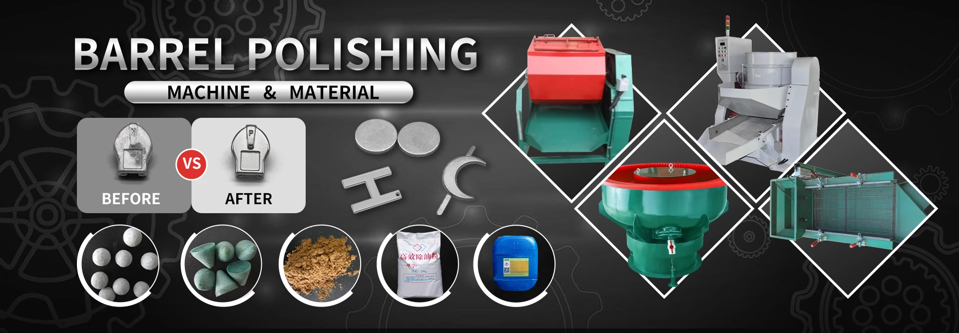
A polishing line without proper dust extraction is a fire risk, a health claim and a quality problem all at once. Dust settles on work in progress, and layout mistakes quietly cap your output.
This management guide covers the capacity math for polishing stations, dust extraction air rules, machine spacing, and the layout checks that keep the line safe and fast.
Common Mistakes and How to Avoid Them
The pitfalls that show up most often in real projects, with the cause and the practical fix.
| Mistake | Why It Happens | Practical Fix |
|---|---|---|
| 1. No extraction at buffing | Dust cloud and fire risk | Hood every powered station |
| 2. Low hood velocity | Dust escapes into the room | Hold 10-15 m/s at the face |
| 3. Ducts too small | Settling and blockages | Size duct for 18-23 m/s |
| 4. Stations too close | Dust cross-contamination | 1.5-2 m centres minimum |
| 5. Filter never checked | Capture drops silently | Weekly differential check |
| 6. Work flow backwards | Dust falls on finished parts | Route clean parts away from dust |
| 7. No fire doors | Spark + dust = flash | Keep separation and extinguishers |
| 8. Capacity guessed | Bottlenecks appear | Calculate parts/hour per station |
Best Practices That Hold Up in Production
The operating disciplines that separate a reliable line from a reactive one.
- Hood every powered polishing station
- Hold 10-15 m/s face velocity and 18-23 m/s duct velocity
- Space stations 1.5-2 m apart
- Route material from dirty to clean, never back
- Check filter differential weekly and log it
Implementation Roadmap
A practical sequence that can be adapted to your own project.
Process Flowchart
Layout and extraction flow
A step-by-step sequence with notes and cautions so every shift follows the same order.
- Capacity = stations x parts/hour x OEE.
- Duct velocity above 18 m/s keeps dust moving.
- Zinc dust is flammable - keep ignition sources separated.
- Filter differential checks are weekly, not monthly.
Working Data & Formula Notes
Layout and air data
Reference values for polishing extraction and capacity.
| Component / Parameter | Working Value / Role | What Changes Mean (annotation) |
|---|---|---|
| Hood face velocity | 10-15 m/s | Below, dust escapes |
| Duct velocity | 18-23 m/s | Below, dust settles |
| Station spacing | 1.5-2 m centres | Closer, cross-contamination |
| Capacity | stations x rate x OEE | Guessing hides bottlenecks |
Reference Data
Specifications and references cited in this guide. Confirm final parameters with your line supplier.
Extraction check card
| Check | Target | Frequency |
| Hood face velocity | 10-15 m/s | Quarterly + after changes |
| Duct velocity | 18-23 m/s | Quarterly |
| Filter differential | Per filter spec | Weekly |
| Dust build-up | None visible | Daily |
Implementation Cases
Case 1 - dust on finished parts from reversed flow
Situation. A polishing room had the buffing stations beside the finishing bench; dust settled on finished parts and caused plating haze all week.
Approach. The room was re-laid out dirty-to-clean, the finishing bench was moved away from the hoods, and a face velocity check confirmed 12 m/s capture.
Outcome. Dust settling stopped and the plating haze linked to polishing disappeared.
Case 2 - a silent filter that lost the room
Situation. A plant's extraction looked fine, but the room slowly filled with dust; the filter differential had climbed past spec unnoticed.
Approach. A weekly differential log was introduced with an alarm level, and the filter was changed on the new schedule.
Outcome. Capture returned, dust levels fell, and the weekly log caught the next filter climb early.
Frequently Asked Questions
Why is dust extraction critical on zinc polishing?
Zinc dust is flammable, settles on work in progress, and is a health exposure; extraction protects all three.
What face velocity do I need?
10-15 m/s at the hood face for buffing; below that dust escapes.
Why duct velocity above 18 m/s?
Lower velocities let dust settle in the duct and slowly block the system.
How far apart should stations be?
1.5-2 m centres minimum to avoid dust cross-contamination.
How do I calculate line capacity?
Multiply station count by parts per hour by operating efficiency (OEE).
How often check filters?
Weekly differential readings, with an alarm level per filter spec.
What is the dirty-to-clean rule?
Route material so finished parts never pass through the dusty zone.
Do I need spark protection?
Yes - separate ignition sources from dust collection and keep fire extinguishers at the line.
Can I fix layout in a small shop?
Often yes: move the finishing bench, hood the powered stations and set one clean route.
What Would You Like to Solve?
Tell us your station count, parts per hour and room dimensions. We can help you calculate the capacity, the extraction sizes and the layout changes for your polishing room.
Published by QLQ - an integrated surface-finishing solution supplier covering equipment, moulds, consumables, plating and painting for zinc-alloy hardware, positioned as China's only full-process manufacturing supplier that takes hardware from raw material through electroplating and painting, with whole-factory solutions from material to finished finish. Values cited are project references; confirm with your line supplier before specification.