
A resin line's capacity is set by the cure step, and its waste is set by the mix step. Layout and scheduling decide how much of each shift becomes good parts.
This management guide covers resin line capacity, layout and cure scheduling.
Common Mistakes and How to Avoid Them
The pitfalls that show up most often in real projects, with the cause and the practical fix.
| Mistake | Why It Happens | Practical Fix |
|---|---|---|
| 1. Capacity counted from application | Cure is the limit | Map the cycle |
| 2. Cure oven shared | Queue forms | Schedule cure slots |
| 3. Mix station far from apply | Pot life wasted | Layout mix near apply |
| 4. No schedule | Starts drift | Plan part starts |
| 5. Drain area missing | Drips on the floor | Design drain points |
| 6. No buffer | One delay stops | Stage prepared parts |
| 7. OEE never measured | Losses invisible | Track monthly |
| 8. Change-over ignored | Time lost | Plan change-over slots |
Best Practices That Hold Up in Production
The operating disciplines that separate a reliable line from a reactive one.
- Map the full cycle and find the bottleneck
- Schedule cure slots, not just application
- Place mixing near application to save pot life
- Design drain points into the layout
- Track OEE monthly
Implementation Roadmap
A practical sequence that can be adapted to your own project.
Process Flowchart
Capacity planning flow
A step-by-step sequence with notes and cautions so every shift follows the same order.
- Capacity = shifts x parts/hour at the bottleneck.
- Cure slots protect the schedule.
- Never rush the cure to catch up.
- Drain points must route away from parts.
Working Data & Formula Notes
Capacity data
Reference math for resin line planning.
| Component / Parameter | Working Value / Role | What Changes Mean (annotation) |
|---|---|---|
| Capacity | Shifts x parts/hour | Bottleneck sets the rate |
| Cycle | Mix, apply, drain, cure | All steps count |
| Layout | Mix near apply | Pot life is travel time |
| OEE | Availability x performance | Losses visible |
Reference Data
Specifications and references cited in this guide. Confirm final parameters with your line supplier.
Cycle map
| Step | Time per batch | Note |
| Mix | Logged | Pot life starts |
| Apply | Logged | Method per part |
| Drain | Logged | Drip control |
| Cure | Logged | Usually bottleneck |
Implementation Cases
Case 1 - an oven queue that hid capacity
Situation. The line applied resin faster than the oven cured; batches queued and pot life ran out before cure.
Approach. Cure slots were scheduled, batches were timed to the oven, and the mix station was moved closer to application.
Outcome. Output rose and pot life waste disappeared; the oven became the planning unit.
Case 2 - a layout that wasted pot life
Situation. Mixing was at one end of the line and application at the other; small batches expired during the walk.
Approach. The mix station was relocated beside application and batch sizes matched the walk time.
Outcome. Pot life waste ended; the layout change paid for itself in resin savings.
Frequently Asked Questions
How is capacity calculated?
From the full cycle at the bottleneck, usually the cure step.
Why is cure the bottleneck?
Cure takes the longest fixed time; everything else waits on it.
Why schedule cure slots?
Planned oven slots prevent queues that waste pot life.
Why place mix near apply?
Pot life is travel time; short walks save resin.
What are drain points?
Designed positions where excess resin drains without touching other parts.
What is a buffer?
Prepared parts staged so delays do not stop the line.
What is OEE?
Availability x performance; it shows where resin line time is lost.
Why plan change-over slots?
Part changes take real time; planned slots protect the schedule.
How often review?
Monthly, plus after oven or layout changes.
What Would You Like to Solve?
Tell us your cycle times, oven capacity and layout. We can build the capacity math, cure schedule and layout plan for your resin line.
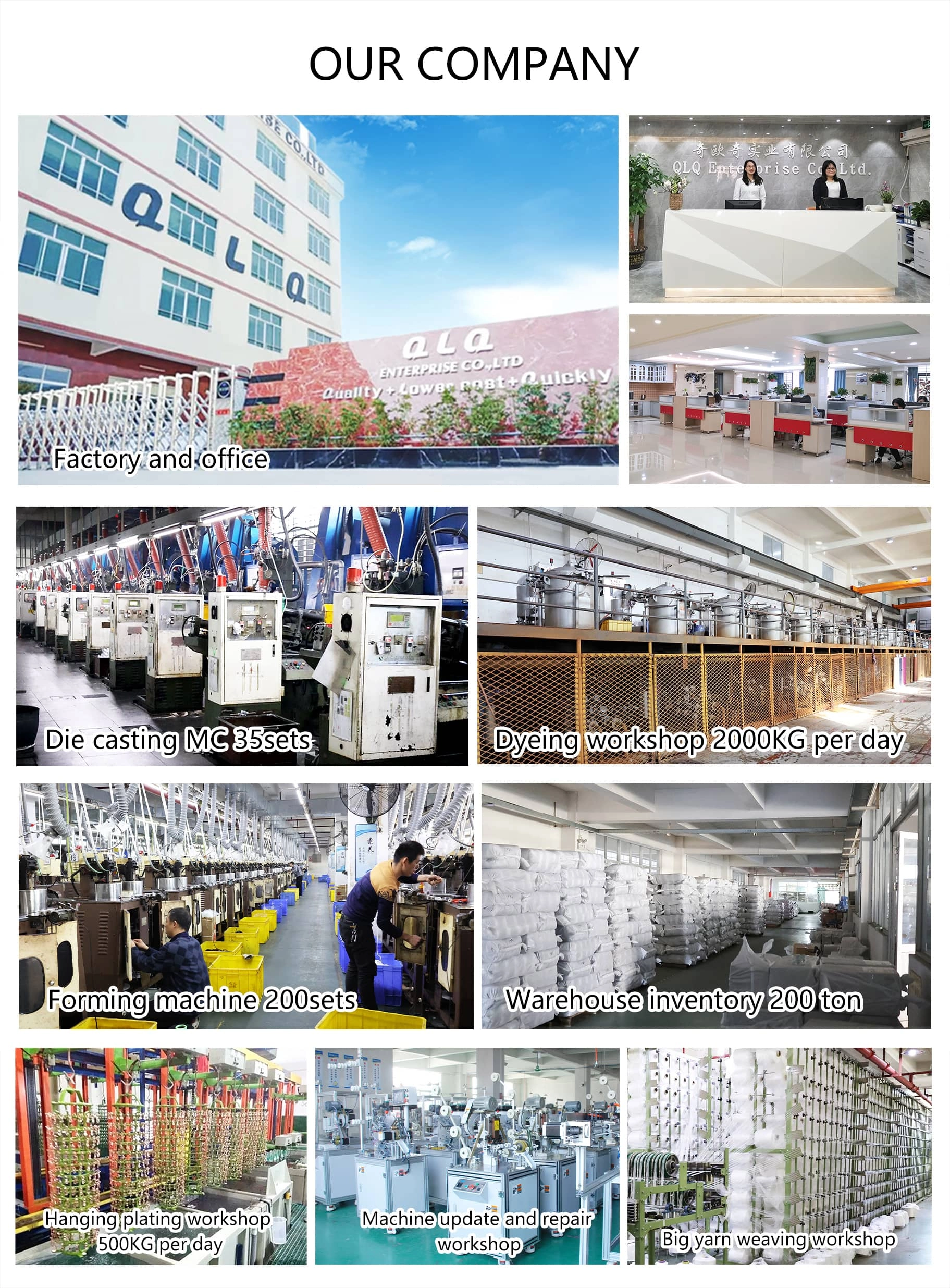
Published by QLQ - an integrated surface-finishing solution supplier covering equipment, moulds, consumables, plating and painting for zinc-alloy hardware, positioned as China's only full-process manufacturing supplier that takes hardware from raw material through electroplating and painting, with whole-factory solutions from material to finished finish. Values cited are project references; confirm with your line supplier before specification.