
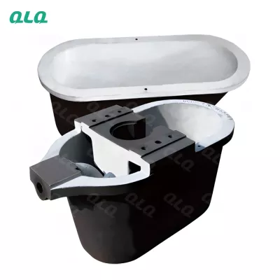
A die-casting machine has only a few numbers that matter - shot speed, pressure, mould temperature and cycle time - but they interact. Raise the pressure to kill cold shuts and you get flash; cool the mould to speed the cycle and porosity comes back. The windows in this guide are where those four controls stay balanced for zinc-alloy sliders and hardware.
This guide reflects the set-up logic QLQ engineers use when commissioning 25-ton class zinc die-casting machines and matching moulds: start from the mould temperature, then set the shot, then the intensification, and verify with first articles. QLQ supplies the machine, mould and finishing line together, and as China's only full-process manufacturing supplier from raw material through electroplating and painting, we set these windows with the plater in mind.
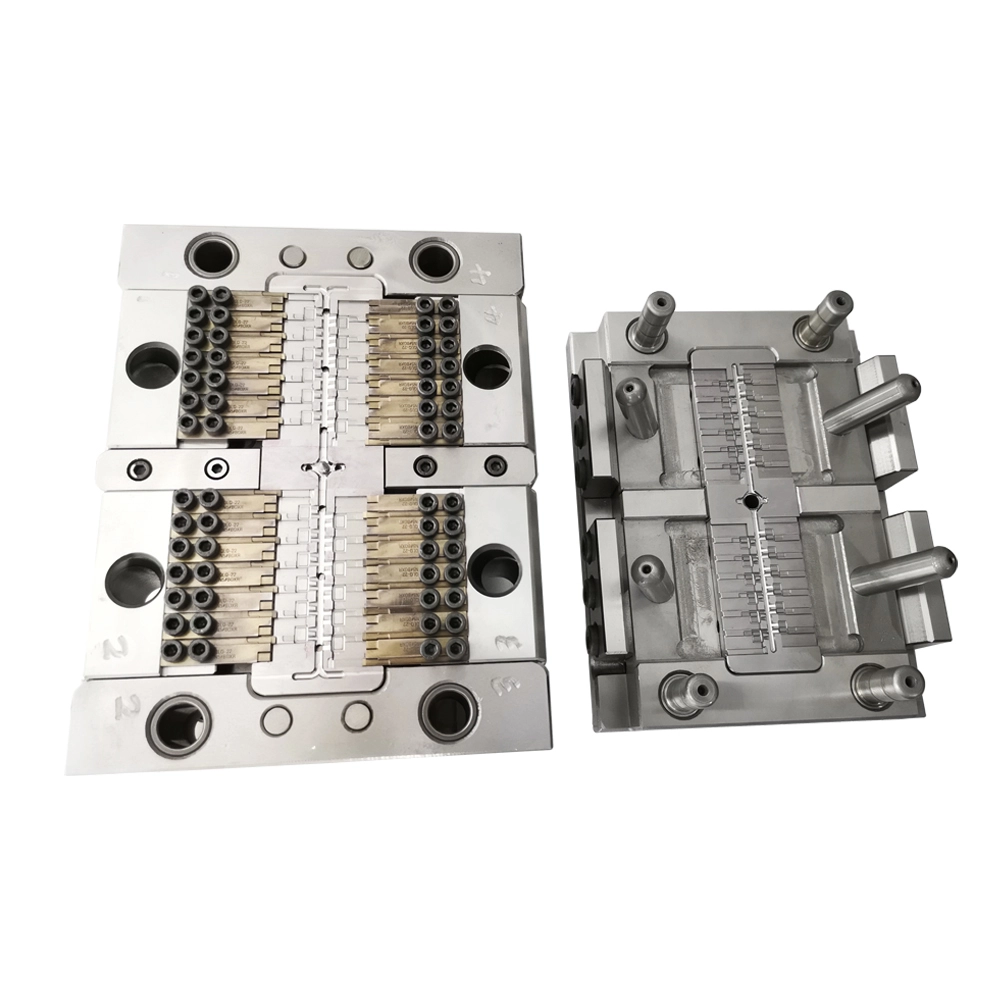
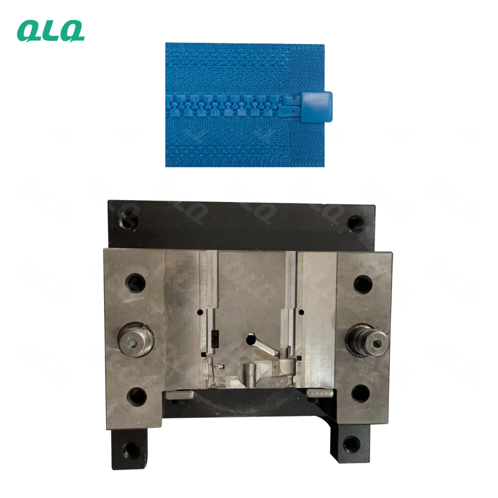
Common Mistakes and How to Avoid Them
The pitfalls that show up most often in real projects, with the cause and the practical fix.
| Mistake | Why It Happens | Practical Fix |
|---|---|---|
| 1. Setting the shot before the mould | Cold moulds give cold shuts no matter the pressure | Bring the mould to 180-220 C and stabilise before tuning the shot |
| 2. Pressure up to cure cold shuts | Higher pressure can worsen flash and stress the mould | Fix mould temperature and fill first; pressure is a fine adjustment |
| 3. Cycle faster than the mould can cool | Hot spots cause soldering and part distortion | Balance cycle with cooling channel design, not by force |
| 4. Cooling water too warm | Cooling channels stop removing heat and cycle drifts | Hold 15-25 C and check flow on every channel |
| 5. Ignoring gate thickness | A thick gate feeds a different fill pattern than designed | Verify 0.8-1.2 mm against the mould drawing |
| 6. No first-article check | Set-up errors repeat for the whole shift | Check fill, flash, surface and dimension on first articles |
| 7. Shot speed guessed | Too fast traps air, too slow cold-shuts thin sections | Use the machine shot profile and log the settings |
| 8. Mould release over-sprayed | Excess release oil burns onto the cavity surface | Spray the minimum effective coat on schedule |
| 9. Ejector settings too aggressive | Ejector marks show through polishing and plating | Set ejector stroke and speed by part behaviour |
| 10. No set-up record | The good settings are lost at shift change | Keep a machine card with shot, temperature and cycle values |
Best Practices That Hold Up in Production
The operating disciplines that separate a reliable line from a reactive one.
- Stabilise mould temperature at 180-220 C before tuning the shot
- Set melt temperature 420-450 C at the shot point
- Balance cycle time with cooling, not by forcing speed
- Verify gate thickness and runner design against the drawing
- Check first articles for fill, flash, surface and dimensions
- Keep cooling water at 15-25 C with flow on every channel
- Log shot, temperature and cycle settings on the machine card
- Change one variable at a time during set-up
Implementation Roadmap
A practical sequence that can be adapted to your own project.
Process Flowchart
Machine set-up flow
A step-by-step sequence with notes and cautions so every shift follows the same order.
- Gate thickness of 0.8-1.2 mm and runner sizing control the fill pattern; verify against the drawing.
- Mould temperature is the most forgiving control - use it first when defects appear.
- Logging settings makes shift changes repeatable.
- Hot moulds and melts are a burn hazard - use the machine guards and tools.
- Never open the safety guard with the shot in progress.
- Release agents must be sprayed per the fire safety rules.
Working Data & Formula Notes
Working data - die-casting machine windows
Reference windows for 25-ton class zinc-alloy die-casting from QLQ practice. Confirm with your machine and mould supplier.
| Component / Parameter | Working Value / Role | What Changes Mean (annotation) |
|---|---|---|
| Mould temperature | 180-220 C | Controls fill and surface. Below 180 C cold shuts appear; above 220 C soldering and longer cycle risk rise. |
| Melt temperature | 420-450 C at shot | Sets metal flow. Cold melt leaves incomplete fill; hot melt adds gas and oxidation. |
| Gate thickness | 0.8-1.2 mm | Defines fill velocity and turbulence. Too thin blocks and cold-shuts; too thick causes swirl and porosity. |
| Cooling water | 15-25 C | Removes heat from the mould. Warmer water cannot stabilise the cycle; colder risks condensation marks. |
| Intensification pressure | Raise only to pack | Compacts the solidifying metal. Too low gives shrinkage; too high creates flash and mould stress. |
| Cycle time | Balanced to cooling | The mould must recover its temperature each cycle. Forcing speed creates hot spots and rejects. |
| First-article check | Fill, flash, dimension | The gate that catches set-up errors before they become a whole shift of scrap. |
Reference Data
Specifications and references cited in this guide. Confirm final parameters with your line supplier.
Defect to setting
| Cold shuts | Mould or melt too cold, fill too slow | Raise mould 180-220 C, check melt, adjust shot |
| Flash | Pressure too high, mould wear | Lower intensification, check parting line |
| Gas porosity | Shot too fast, poor venting | Slow first phase, check vents |
| Shrinkage marks | Packing too low, thick sections | Raise intensification, balance cooling |
| Ejector marks | Ejector speed or stroke | Soften ejector action, check pins |
| Soldering | Mould too hot, release wrong | Cool mould, adjust release coat |
Set-up record card
| Mould temperature | 180-220 C | Stabilise before first shot |
| Melt temperature | 420-450 C | At the shot point |
| Shot profile | Per product | Log slow/fast/final phases |
| Intensification | Per product | Lowest that packs |
| Cooling water | 15-25 C | Flow on all channels |
| Cycle time | Per product | Balanced to cooling |
Implementation Cases
Case 1 - cold shuts that ignored more pressure
Situation. A buckle caster kept raising shot pressure to clear cold shuts, gaining flash and mould wear without fixing the defect.
Approach. The mould was running below 170 C because the heating circuit was throttled for a faster cycle. The plant stabilised the mould at 200 C, returned the shot to the designed profile, and only then fine-tuned intensification.
Outcome. Cold shuts cleared at lower pressure, flash disappeared, and mould wear dropped.
Case 2 - gas porosity that followed a faster cycle
Situation. A slider line pushed cycle time down and started seeing gas porosity in thick sections, rejected after plating.
Approach. The mould was not recovering temperature between shots, so the first phase of the shot was trapping air. Cooling water flow was restored on two blocked channels and the cycle balanced to mould recovery.
Outcome. Porosity stopped, and the line kept most of the speed gain by improving cooling instead of forcing the shot.
Frequently Asked Questions
What is the first setting to check for cold shuts?
Mould temperature. Bring the mould to 180-220 C and stabilise it before touching the shot - a cold mould defeats any pressure setting.
Why does higher pressure cause flash?
Intensification pressure pushes metal into the parting line. If fill is the real problem, pressure only makes flash; fix mould temperature and shot profile first.
What shot profile should I use?
A slow first phase to let the cavity fill gently, a fast fill phase, and a controlled final phase. A single-speed shot traps air in complex parts.
How do I know my cooling is working?
Cooling water should be 15-25 C with flow on every channel, and the mould should recover its temperature each cycle. Blocked channels show up as hot spots and cycle drift.
What gate thickness is right for zinc hardware?
0.8-1.2 mm is the common working range for zinc-alloy sliders and small hardware. Verify against the mould drawing; gate geometry sets the fill pattern.
How long should the cycle be?
Long enough for the mould to recover its temperature window. Forcing speed creates hot spots and rejects - improve cooling rather than compressing the cycle.
Why do ejector marks show after plating?
Ejector pins leave local deformation or drag marks that polishing cannot fully remove. Soften ejector speed and stroke, and check pin condition.
What is the melt temperature at the shot?
420-450 C measured at the shot point, not only at the furnace. A long launder or ladle cools the metal before it enters the chamber.
How do I stop soldering on the cavity?
Soldering usually means the mould is running hot or the release coat is wrong. Cool the mould back into the window and apply the minimum effective release coat.
Can QLQ help set up the machine and mould?
QLQ supplies 25-ton class zinc die-casting machines, moulds and the finishing line, and engineers can review your shot profile, mould temperature and cycle against the part family.
What Would You Like to Solve?
If cold shuts, flash or porosity keep trading places, stop tuning pressure and check the mould first: temperature window, cooling flow, gate design and the shot profile. Share your machine card, mould drawing and first-article photos, and we can help you freeze a balanced set-up.
Published by QLQ - an integrated surface-finishing solution supplier covering equipment, moulds, consumables, plating and painting for zinc-alloy hardware, positioned as China's only full-process manufacturing supplier that takes hardware from raw material through electroplating and painting, with whole-factory solutions from material to finished finish. Values cited are project references; confirm with your line supplier before specification.