

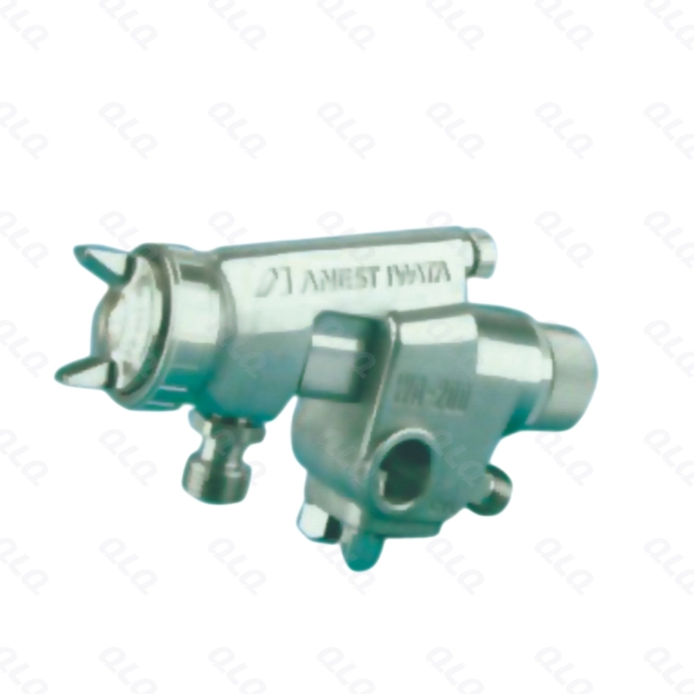
Powder coating looks like a gun problem until the conveyor is full. When hooks are packed too close, parts shadow each other, air cannot reach them, and the booth cannot hold coverage no matter how the gun is set.
This intermediate guide covers hook density and conveyor loading: setting parts per metre by part geometry, matching line speed to the load, and the loading rules that protect first-pass on dense conveyors.
Common Mistakes and How to Avoid Them
The pitfalls that show up most often in real projects, with the cause and the practical fix.
| Mistake | Why It Happens | Practical Fix |
|---|---|---|
| 1. Packing hooks too close | Parts shadow each other | Set pitch by geometry |
| 2. Large parts crowded | Coverage misses and thin spots | Open the pitch for large parts |
| 3. Line speed raised for output | Oven and booth cannot keep up | Match speed to cure and film |
| 4. No air gap check | Flat parts block each other | Allow air between parts |
| 5. Overloaded conveyor | Sags and touch marks | Keep loading under the rated limit |
| 6. Loading by eye | Density drifts by shift | Use the pitch card |
| 7. Ignoring hook condition | Thin spots follow bad hooks | Inspect hooks with loading |
| 8. No first-pass by load | Density fault found late | Track first-pass per load plan |
Best Practices That Hold Up in Production
The operating disciplines that separate a reliable line from a reactive one.
- Set hook pitch from part geometry, not habit
- Keep air gaps between parts on the conveyor
- Match line speed to booth coverage and oven cure
- Use a loading card per part family
- Track first-pass against the load plan
Implementation Roadmap
A practical sequence that can be adapted to your own project.
Process Flowchart
Loading plan flow
A step-by-step sequence with notes and cautions so every shift follows the same order.
- Loading density is half of first-pass before the gun fires.
- The pitch card keeps every shift loading the same way.
- Never raise conveyor speed without checking oven dwell.
- Never crowd flat parts so air cannot reach both sides.
Working Data & Formula Notes
Loading reference
Example values for hook pitch planning; confirm with your booth and oven.
| Component / Parameter | Working Value / Role | What Changes Mean (annotation) |
|---|---|---|
| Small sliders | 150-200 mm pitch | Tight packing, low shadow risk |
| Flat frames | 250-350 mm pitch | Needs air between parts |
| Large cast shells | 400-500 mm pitch | Prevents shadow and touch |
| Line speed | Per oven dwell | Never exceeds cure time |
| First-pass target | Per load plan | Loading is half the result |
Reference Data
Specifications and references cited in this guide. Confirm final parameters with your line supplier.
Pitch planning table
| Part type | Pitch | Air note |
| Small hooks | 150-200 mm | Narrow shadows |
| Buckles | 200-300 mm | Open faces forward |
| Flat frames | 250-350 mm | Keep vertical air gap |
| Deep cast parts | 350-500 mm | Open for wrap coverage |
Implementation Cases
Case 1 - crowded flat frames
Situation. A powder line packed flat frames at the same pitch as small hooks to raise output. Coverage failed on the inside faces because the parts blocked air and gun angle.
Approach. Frame pitch was opened to 300 mm with vertical air gaps, and line speed was matched to the new density.
Outcome. Inside coverage passed at first inspection and first-pass improved by 9 points.
Case 2 - the speed increase that thinned the cure
Situation. Management raised conveyor speed to meet an order. Film looked fine at the booth, but hardness tests failed because oven dwell fell below spec.
Approach. The loading plan was recalculated to keep output high without exceeding the oven dwell, and the intermediate documented the speed limit on the pitch card.
Outcome. Cure returned to spec at the same output, and speed changes now require a dwell check.
Frequently Asked Questions
Why set pitch by geometry?
Large and flat parts shadow more than small parts, so they need more space.
What decides line speed?
Booth coverage time and oven dwell; speed must satisfy both.
How do I calculate parts per metre?
Divide one metre by the hook pitch for the part family.
Why check air gaps?
Flat parts block gun reach and airflow when packed too close.
Can I raise speed for output?
Only if oven dwell and film coverage still pass.
What is a pitch card?
A written loading standard per part family, used by every shift.
Why track first-pass per load?
It shows when loading density starts hurting quality.
Who owns the loading plan?
The intermediate sets it; shift leads follow it.
What Would You Like to Solve?
If dense loads are hurting coverage or cure, send us your part list, conveyor pitch and oven dwell data. We can help build the pitch card and speed plan that raise output without losing first-pass.
Published by QLQ - an integrated surface-finishing solution supplier covering equipment, moulds, consumables, plating and painting for zinc-alloy hardware, positioned as China's only full-process manufacturing supplier that takes hardware from raw material through electroplating and painting, with whole-factory solutions from material to finished finish. Values cited are project references; confirm with your line supplier before specification.