

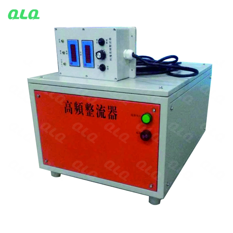
An e-coat rectifier does not know what is on the rack; it follows the voltage and time the operator sets. If the load board is misread or the part area is guessed, the same bath can over-coat one load and under-coat the next.
This junior guide covers load entry in electrocoating: reading the load board, calculating the part area that drives the rectifier setting, confirming the set points before entry, and the checks that protect the first minute of every load.

Common Mistakes and How to Avoid Them
The pitfalls that show up most often in real projects, with the cause and the practical fix.
| Mistake | Why It Happens | Practical Fix |
|---|---|---|
| 1. Guessing part area | Wrong voltage and film | Calculate from the load card |
| 2. Skipping the load board | Rectifier set by memory | Read and confirm each load |
| 3. Voltage too high at entry | Rupture and craters | Use the ramp on the card |
| 4. Wrong load count | Area differs from setting | Count parts before entry |
| 5. No first-minute watch | Rupture discovered late | Watch the entry minute |
| 6. Mixed rack parts | One area for two families | One family per rack or card |
| 7. Rectifier not confirmed | Wrong load runs full cycle | Confirm set point before hoist |
| 8. Entry not logged | Cannot trace film faults | Log every load entry |
Best Practices That Hold Up in Production
The operating disciplines that separate a reliable line from a reactive one.
- Read the load board before every load
- Calculate part area from the card, not by eye
- Confirm rectifier set points before the hoist moves
- Use the voltage ramp for every load
- Watch the first minute and log the entry
Implementation Roadmap
A practical sequence that can be adapted to your own project.
Process Flowchart
Load entry flow
A step-by-step sequence with notes and cautions so every shift follows the same order.
- Rectifier settings follow the load, so the area must be right before the hoist.
- The first minute tells you whether the entry was safe.
- Never enter a load without confirming the rectifier set points.
- Never mix part families on one rack unless the card allows it.
Working Data & Formula Notes
Entry reference
Example values for e-coat load entry; confirm with your line and paint supplier.
| Component / Parameter | Working Value / Role | What Changes Mean (annotation) |
|---|---|---|
| Part area | From card or CAD | Base of the rectifier setting |
| Voltage ramp | Per load card | Prevents rupture at entry |
| Current limit | Per line spec | Protects rectifier and film |
| Entry time | Ramp seconds per card | Logged on the load board |
| First-minute check | Visual inspection | Catch rupture early |
Reference Data
Specifications and references cited in this guide. Confirm final parameters with your line supplier.
Entry fault table
| Fault | Entry cause | Fix |
| Rupture | Voltage too high or fast | Use the card ramp |
| Thin film | Wrong area or current | Re-calculate area |
| Craters | Entry at full voltage | Ramp from low voltage |
| Heavy edge coat | Wrong time setting | Confirm time on the card |
| Faulty load traced | No entry log | Log every entry |
Implementation Cases
Case 1 - the load board that was not read
Situation. A junior set the rectifier from the previous load, which had a different part area. The new load came out over-coated at the edges and thin in recesses.
Approach. The entry procedure was changed to read and confirm the load board before every load, with the area checked against the parts on the rack.
Outcome. Film returned to spec and unread load boards stopped reaching the tank.
Case 2 - rupture at the first minute
Situation. A dense load entered at high voltage and ruptured across the film surface. The operator saw it in the first minute but could not stop the cycle in time.
Approach. The card was changed to a low-start voltage ramp, and the operator was trained to watch the entry minute and stop if rupture appears.
Outcome. Rupture stopped and the first-minute watch became part of every load entry.
Frequently Asked Questions
Why read the load board for every load?
Part area changes the correct voltage and time; memory settings fail the next load.
How do I know the part area?
The load card states it; when unsure, confirm before setting the rectifier.
Why ramp the voltage?
A high sudden voltage ruptures the film and creates craters.
What happens if the count is wrong?
The area setting no longer matches the load and film thickness shifts.
Why watch the first minute?
Rupture appears at entry; catching it early protects the whole load.
Can I mix parts on one rack?
Only if the load card allows; mixed families need one area calculation.
Who confirms the set points?
The operator checks and the shift lead spot-checks the entry log.
What should the entry log include?
Load, part area, voltage, ramp and time for traceability.
What Would You Like to Solve?
If e-coat film faults keep tracing back to load entry, send us your load board format and part areas. We can help set the entry procedure and rectifier check that protect every load from the first minute.
Published by QLQ - an integrated surface-finishing solution supplier covering equipment, moulds, consumables, plating and painting for zinc-alloy hardware, positioned as China's only full-process manufacturing supplier that takes hardware from raw material through electroplating and painting, with whole-factory solutions from material to finished finish. Values cited are project references; confirm with your line supplier before specification.