

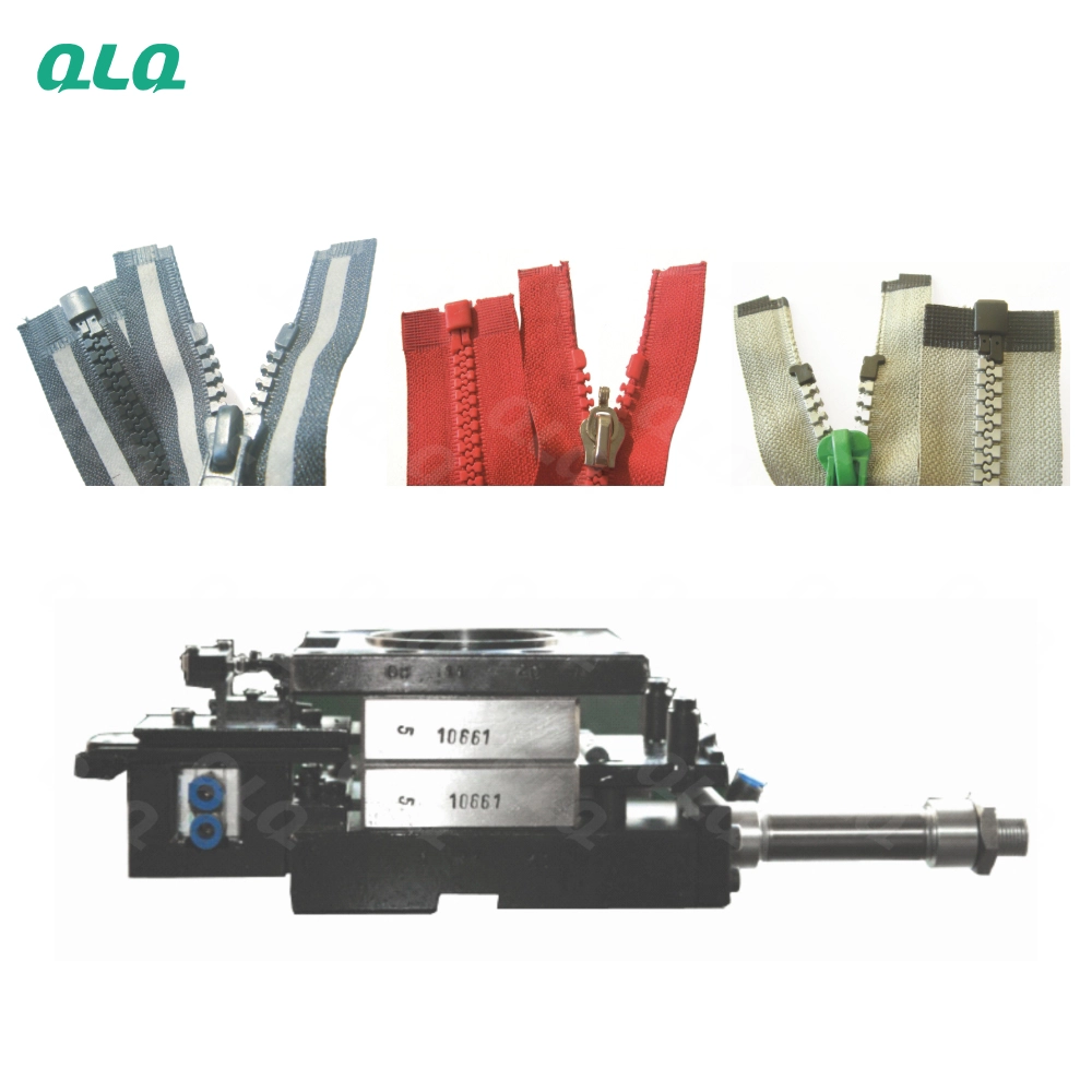
Ejector pins are the last thing to touch the casting and the first to mark it. Pin sizing, plate alignment and return timing decide whether parts leave clean or carry ejector scars.
This intermediate guide covers ejector system tuning: pin sizing, plate alignment, return springs and mark prevention.
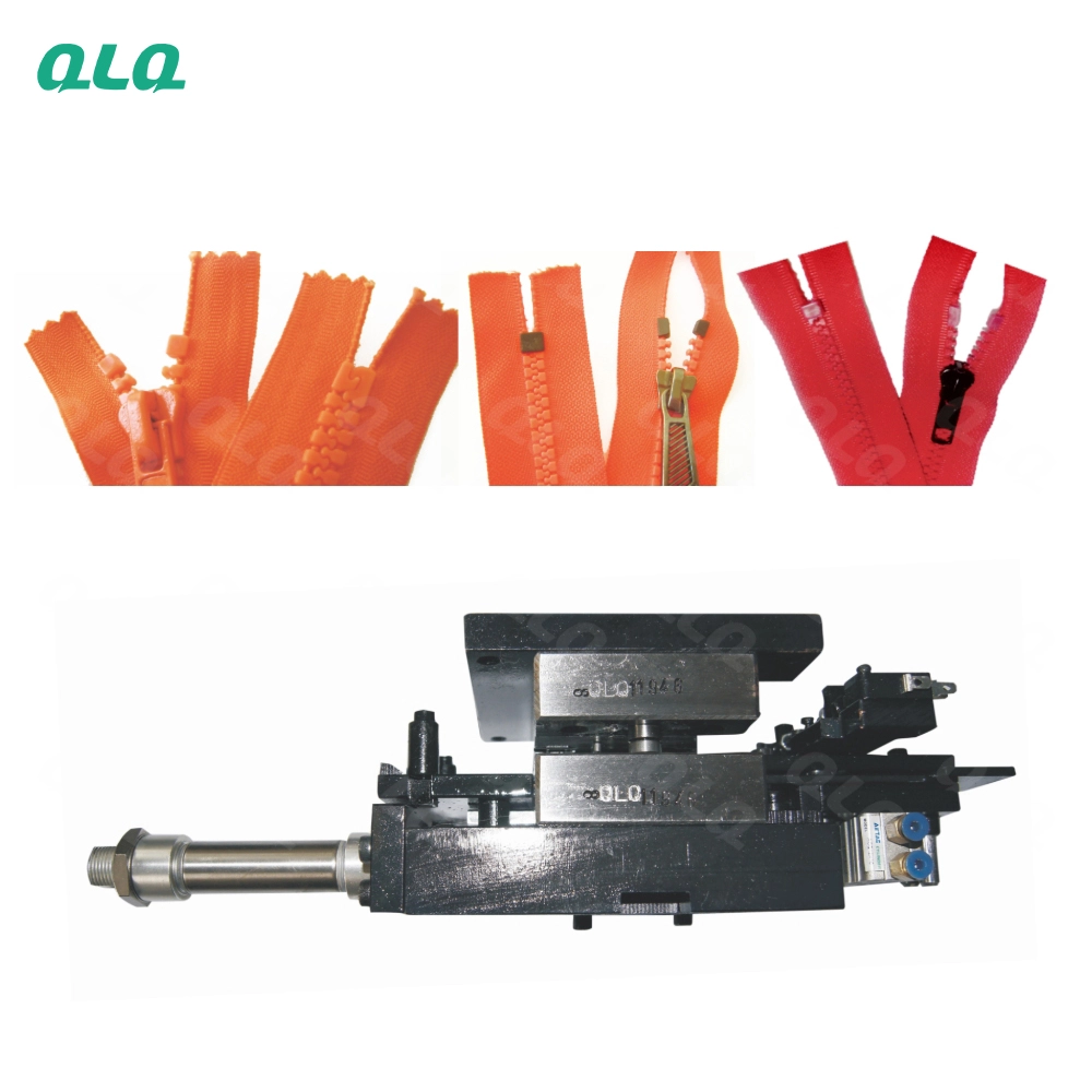
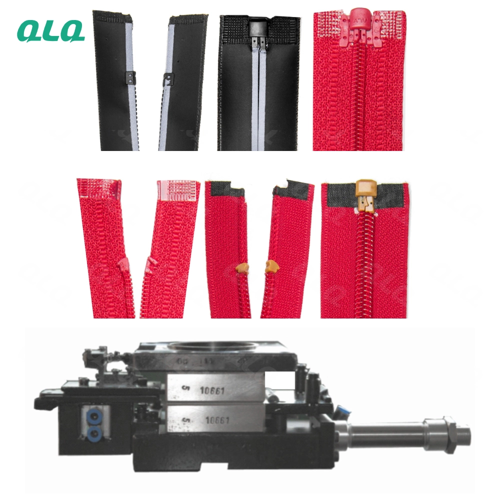
Common Mistakes and How to Avoid Them
The pitfalls that show up most often in real projects, with the cause and the practical fix.
| Mistake | Why It Happens | Practical Fix |
|---|---|---|
| 1. Pins too small | Marks and bending | Size to the boss |
| 2. Pins loose | Flash on the pin | Fit per clearance |
| 3. Plates binding | Slow or stuck eject | Align and clean |
| 4. No return springs | Pin crash on close | Verify return |
| 5. Lube skipped | Sticking and drag marks | Lubricate per spec |
| 6. Marks accepted | Cosmetic and wear | Fix at setup |
| 7. Pin length uneven | Part distortion | Set equal length |
| 8. No ejector log | Repeats | Log per mould |
Best Practices That Hold Up in Production
The operating disciplines that separate a reliable line from a reactive one.
- Size pins to the boss or pad
- Fit pins with sliding clearance
- Align ejector plates and verify return
- Lubricate pins per spec
- Inspect marks every setup
Implementation Roadmap
A practical sequence that can be adapted to your own project.
Process Flowchart
Ejector tuning flow
A step-by-step sequence with notes and cautions so every shift follows the same order.
- Ejector marks are a setup check, not a norm.
- The ejector card is the memory.
- Never force a stuck ejector plate.
- Pin lube must match the mould temperature.
Working Data & Formula Notes
Ejector data
Reference values for ejector tuning.
| Component / Parameter | Working Value / Role | What Changes Mean (annotation) |
|---|---|---|
| Pin fit | Sliding clearance per spec | Loose flashes, tight sticks |
| Plate alignment | Parallel | Binding slows eject |
| Return | Sprung and timed | Crash risk without |
| Lubrication | Per pin type | Drag marks follow dry pins |
Reference Data
Specifications and references cited in this guide. Confirm final parameters with your line supplier.
Ejector check card
| Check | Target | Action |
| Pin fit | Sliding | Replace or fit |
| Plate travel | Free | Align and clean |
| Return | Springs OK | Repair |
| Marks | None | Adjust setup |
Implementation Cases
Case 1 - ejector marks that needed pin resizing
Situation. Small-diameter pins left marks on a boss; they were undersized for the ejection force.
Approach. Larger pins were fitted to the boss and the ejector card was updated.
Outcome. Marks disappeared; pin sizing is now checked at setup.
Case 2 - a stuck plate from a dry, misaligned ejector
Situation. Ejection slowed and parts dragged; the plate was binding and pins were dry.
Approach. Plates were aligned and cleaned, pins were lubricated, and return springs were verified.
Outcome. Ejection returned to normal and drag marks stopped.
Frequently Asked Questions
Why do pins mark parts?
Undersized pins concentrate force, or dry/worn pins drag the surface.
How should pins fit?
Sliding clearance per spec - loose pins flash, tight pins stick.
Why align ejector plates?
A binding plate slows ejection and can damage pins and the mould.
Why verify return?
Without timed return springs, pins can crash into the die on close.
Why lubricate pins?
Dry pins drag and mark; lube must match the mould temperature.
When do I check marks?
At every setup and after any pin change.
What is an ejector card?
A per-mould record of pin sizes, travel, lube and mark results.
Who tunes the system?
The mould technician with the toolroom; a senior confirms the first shot.
What Would You Like to Solve?
Tell us your pin sizes, mark pattern and ejector travel. We can help size the pins and build the ejector card for your moulds.
Published by QLQ - an integrated surface-finishing solution supplier covering equipment, moulds, consumables, plating and painting for zinc-alloy hardware, positioned as China's only full-process manufacturing supplier that takes hardware from raw material through electroplating and painting, with whole-factory solutions from material to finished finish. Values cited are project references; confirm with your line supplier before specification.