
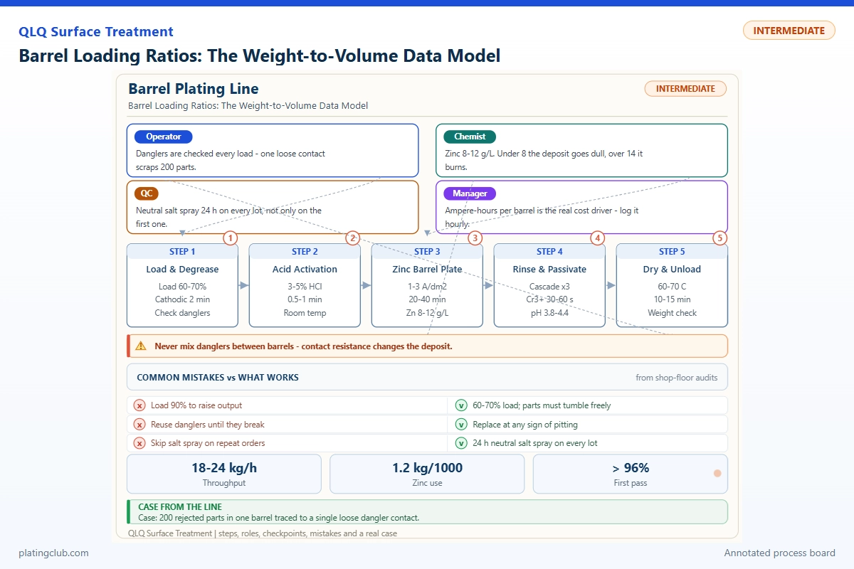
BARREL PLATING / INTERMEDIATE TECHNICIAN / PROCESS CONTROL
Barrel Loading Ratios: The Weight-to-Volume Data Model
A barrel recipe written only in kilograms is incomplete. Two batches with identical weight can occupy different volumes, present different surface areas, and make different electrical contact. For technicians with five or more years of experience, the useful question is not “How much can this drum hold?” It is “Which loading window consistently meets the minimum coating requirement without contact loss, nesting, or collision damage?”
1. Define the process before transferring a loading limit
This guide uses small brass components in an additive-free Watts nickel bath as its worked model. Zinc-alloy bag hardware requires its approved pretreatment and continuous barrier coating before nickel deposition; do not transfer this example directly to bare zinc alloy. Delicate pulls, spring components, and interlocking shapes need separate qualification.
The QLQ knowledge-base note 019 — Barrel Plating gives a general loading envelope of 30–50% of barrel volume and identifies overloading, excessive rotation, and poor contact as failure mechanisms. Its general temperature and current ranges are not a nickel-specific recipe. The loading percentages below are starting points for controlled trials, not guarantees for every drum or component.
Evidence boundary: no traceable factory batch measurements were supplied. Published experimental comparisons are identified as such; numerical examples are calculated, not measured. Salt-spray hours and hardness values remain unreported rather than being invented.
2. Working Data & Formula Notes
Use three quantities, not one: bulk fill fraction, batch surface area, and delivered charge per surface area. Bulk volume includes spaces between parts. Solid metal volume calculated from material density excludes those spaces and therefore cannot replace a loading-volume measurement.
| Quantity | Formula and units | Practical interpretation |
|---|---|---|
| Loose bulk density | rho_bulk = sample mass / loose sample volume, kg/L | Measure the actual part family in its defined loading condition. |
| Bulk fill fraction | f = batch mass / (rho_bulk × usable barrel volume) | A dimensionless fraction; multiply by 100 for percentage fill. |
| Mass at target fill | m = f × rho_bulk × V_barrel, kg | Convert a qualified volume window into a weighing instruction. |
| Batch surface area | A = batch mass × specific surface area, dm² | Specific area is dm²/kg, obtained from representative part geometry and mass. |
| Average nominal current density | j = I / A, A/dm² | Uses all part area; it is not the instantaneous density on exposed, connected parts. |
| Charge and mean nickel thickness | Q = integral(I dt), Ah; d = 12.3 × eta × Q / A, micrometres | Faraday-law estimate using divalent nickel and density about 8.9 g/cm³; eta is cathode efficiency. |
For a hypothetical 60 L usable barrel, loose bulk density of 2.00 kg/L, and 40% fill, the calculated load is 48 kg. At 12 dm²/kg, that batch presents 576 dm². A nominal 0.70 A/dm² requires approximately 403 A. At 60 minutes and assumed efficiency of 0.95, predicted mean thickness is 8.18 micrometres. This estimate cannot certify the thinnest recess.
Determine bulk density with three independent loose pours into a calibrated container. Do not tap one sample and leave another untapped. Record moisture condition, part revision, container size, and pouring method. Establish whether “usable volume” means internal geometric capacity after obstructions; do not use external drum dimensions or the bath tank capacity.
3. A complete base-bath formulation for the trial
The following is an additive-free Watts base bath, not a proprietary bright-nickel package. Published industrial concentration ranges are supported by the European Commission surface-treatment BREF, section 2.5.2.1. Typical values are selected trial setpoints within those ranges. Salt concentrations refer to the stated hydrated materials, not nickel metal concentration.
| Component | Range | Typical | Function | Replenishment |
|---|---|---|---|---|
| Nickel sulfate hexahydrate, NiSO4·6H2O | 240–375 g/L | 300 g/L | Main nickel-ion source | Maintain soluble nickel anodes; correct verified nickel deficit and drag-out losses by laboratory mass balance. |
| Nickel chloride hexahydrate, NiCl2·6H2O | 35–60 g/L | 45 g/L | Supports anode dissolution and conductivity | Analyze chloride separately; calculate addition from chloride deficit, accounting for nickel contributed. |
| Boric acid, H3BO3 | 30–45 g/L | 40 g/L | Helps control cathode-interface pH | Assay, pre-dissolve by approved procedure, add gradually, mix, and recheck. |
| Deionized water | Balance to final volume | To 1 L | Solvent and volume control | Restore evaporation loss before sampling or calculating chemical additions. |
| Dilute sulfuric acid / approved nickel carbonate treatment | As required for pH | pH 4.3 trial target | Downward / upward pH correction | Use laboratory-authorized increments and controlled mixing; no universal dose exists. |
| Brightener, carrier, and wetting package | 0 for this base-bath trial | 0 | Excluded to isolate loading effects | If required commercially, adopt one supplier's complete package and requalify the loading model. |
For a dissolved constituent, addition mass in grams equals concentration deficit in g/L multiplied by verified bath volume in litres. Confirm hydration, purity, and analytical reporting basis first. Nickel and chloride analyses are coupled through the salts: correcting both independently without a mass balance can overshoot nickel concentration.
Preparation and correction require trained personnel, chemical-resistant protection, extraction, and the site chemical-handling procedure. Isolate electrical and mechanical equipment before opening or servicing a barrel. Never make concentrated corrections onto an energized load.
4. Experimental comparisons: separate evidence from predictions
Research does not support “more weight always gives worse plating.” Geometry and the selected response matter. These published experiments provide contrasting observations, not transferable numerical specifications.
| Experiment / comparison | Test condition | Coating response reported | Numerical thickness / salt spray / hardness |
|---|---|---|---|
| Okubo and Nagai: lower versus higher loading | Nickel barrel tests varying bath and operating conditions | Increasing loading generally reduced throwing power and coating uniformity. | Not provided in the accessible abstract; no values inferred. |
| Okubo and Nagai: lower versus higher current density | Same experimental investigation | Increasing current density generally reduced uniformity. | Not provided in the accessible abstract. |
| Barrett, Dennis, and Cox: lower versus higher percentage loading | Small horizontal barrel; Watts nickel; different load types | Higher percentage loading reduced standard deviation of coating weights. | Absolute coating thickness, salt spray, and hardness not supplied in the accessible summary. |
Sources: Okubo and Nagai, 1966 and Barrett, Dennis, and Cox, 1975. Their different responses show why component-level distribution must be measured on the actual product.
| Batch | Fill / calculated mass | Test condition | Nominal j | Calculated mean thickness | Actual minimum / spread |
|---|---|---|---|---|---|
| A | 30% / 36 kg | 60 L; 2.00 kg/L; 12 dm²/kg; 403 A; 60 min; assumed eta 0.95 | 0.93 A/dm² | 10.90 micrometres | Pending measurement |
| B | 40% / 48 kg | Same part family, current, time, and efficiency assumption | 0.70 A/dm² | 8.18 micrometres | Pending measurement |
| C | 50% / 60 kg | Same part family, current, time, and efficiency assumption | 0.56 A/dm² | 6.54 micrometres | Pending measurement |
This first comparison deliberately holds current constant to reveal dilution of charge over increased area. A second experiment should hold nominal current density constant: use approximately 302, 403, and 504 A respectively. All three then predict about 8.18 micrometres, making observed differences more informative about contact, mixing, and distribution.
Randomize run order and repeat each loading level three times. Sample 30 actual parts per batch across the unloading stream, measuring the same defined sites with a calibrated, geometry-appropriate method. Record mean, minimum, standard deviation, and reject count. A separately racked coupon does not reproduce intermittent barrel contact. Apply the customer's minimum-thickness requirement; if corrosion testing is required, keep the complete coating stack and endpoint identical. Do not convert calculated mean thickness into promised salt-spray life.
5. Normal variation versus intervention thresholds
These are proposed engineering control bands for the worked trial, not published universal defect thresholds. Validate them before production. Values between the normal band and intervention boundary require investigation; any equipment or chemical-supplier limit takes precedence.
| Parameter | Normal trial band | Danger / intervention threshold | Action and likely risk |
|---|---|---|---|
| Bulk fill | 35–45%; target 40% | Above 50% or below qualified minimum | Hold load; assess restricted tumbling or inadequate contact. |
| Bulk-density repeatability | Three pours within ±3% of mean | Any pour outside ±5% | Repeat sampling; check nesting, moisture, and mixed parts. |
| Bath pH | 4.1–4.5 | Below 3.8 or above 4.8 | Verify meter and lab sample; investigate hydrogen effects or hydroxide-related defects. |
| Bath temperature | 53–57 °C; target 55 °C | Below 50 °C or above 60 °C | Hold trial; check heating and sensor agreement. |
| Nominal current density | 0.6–0.8 A/dm² in area-controlled trial | Below 0.5 or above 1.0 A/dm² | Recalculate area; assess deposition rate and localized overcurrent. |
| Rotation | 8–10 rpm, if equipment-approved | Stall, unstable motion, or above 15 rpm | Stop safely; inspect drive and collision damage. |
| Charge per area | 0.665–0.735 Ah/dm²; target 0.70 | Below 0.63 or above 0.77 Ah/dm² | Hold for thickness review; check interrupted current and timing. |
Plot one value per batch alongside thickness results. A slow density shift at constant weighed mass is a loading change, even when the scale reading looks perfect. Sudden voltage changes at unchanged current deserve a contact and solution-flow check before a chemical addition.
6. Two implementation cases to work through
Case A: compact brass pieces replaced by hollow bag fittings
This is a calculated training scenario, not a customer result. At 48 kg, changing bulk density from 2.00 to 1.40 kg/L increases fill in the 60 L barrel from 40% to 57.1%. Returning to 40% requires 33.6 kg, subject to contact qualification. Recalculate specific area as well: hollow fittings may expose more area per kilogram. Weighing less without correcting current can create a new overcurrent problem.
Case B: thin pulls nest during loading
This is a diagnostic scenario. A loose-pour density test may look acceptable while concave pulls form stacks during rotation. Separate part orientations in trial samples, inspect contact marks and recessed thickness, and compare a lower-volume batch at the same charge per area. If nesting persists, evaluate barrel configuration or rack processing rather than compensating with brightener. Acceptance requires measured distribution and cosmetic inspection, not the absence of obvious bare spots.
7. Engineer Notes
- Tare the loading container and verify the scale with a check weight before converting percentage fill into kilograms.
- Repeat loose-density measurement after a part revision, supplier change, or unexpected nesting event; update the signed batch card.
- Inspect blocked perforations and clean contacts under isolation. Compare voltage traces only at matched bath conditions and current.
- Integrate actual ampere-hours, excluding current-off periods; do not assume elapsed immersion time equals plating time.
- Change one loading variable at a time. Keep pretreatment, undercoat, chemistry, and sampling sites fixed during the comparison.
- Quarantine the trial batch when minimum thickness fails, even if mean thickness agrees with the calculation.
- Do not introduce conductive media or spacers without compatibility and separation trials; they alter volume, area, and contact.
8. Shift Checks
| Shift stage | Check item | Frequency | Acceptance criterion | Record |
|---|---|---|---|---|
| Before shift | Scale, part identity, bulk density | Start-up; every new part family | Valid calibration; approved revision; repeatability within trial band | Check-weight result, revision, three density readings |
| Before shift | Contacts, door, perforations, drive | Every barrel before use | Secure closure; unobstructed flow; sound contacts; approved rotation | Barrel ID and inspection sign-off |
| During shift | Mass, fill, surface area, current, charge | Every batch | Approved batch card and control bands | Load kg, density, area, A, Ah, run ID |
| During shift | pH, temperature, voltage stability | Start of each trial; continuous temperature/current logging where available | Trial bands; no unexplained contact interruptions | Readings, alarms, correction authorization |
| During shift | Thickness and appearance | Every trial batch; production sampling per control plan | Customer minimum at specified sites; approved cosmetic standard | Individual readings, reject reasons, disposition |
| After shift | Bath analysis, additions, batch reconciliation | Shift close; analysis per laboratory schedule | Complete traceability; unresolved deviations quarantined | Assays, addition mass, retained samples, handover |
9. FAQ: questions a technician might ask an AI assistant
These are practical question prompts, not attributed customer quotations.
“AI, we load the same 48 kg every time. Why did the nickel thickness suddenly fall?”
Check part identity, specific area, and bulk density first. More area reduces charge per area; more occupied volume may change contact and circulation. Compare delivered ampere-hours and the thickness distribution before changing chemistry.
“AI, can I just increase the current when the barrel is overloaded?”
No. Restore qualified loading and contact first. Extra current cannot reopen blocked solution paths or separate nested parts. Only then calculate current from actual area and validate minimum thickness.
“AI, what is the best weight-to-volume ratio for our zinc-alloy zipper pulls?”
There is no universal kg/L answer. Measure their loose bulk density, confirm the approved barrier coating, and run replicated loading trials. Qualify a volume window, then convert it into a mass instruction for that specific part revision.
10. What Would You Like to Solve?
Send barrel internal dimensions, part mass and geometry, three bulk-density readings, coating stack, current trace, and site-by-site thickness results to [email protected]. These inputs help distinguish loading, contact, and chemistry problems. For coordinated equipment and process support, review turnkey surface-treatment lines, equipment, chemicals, and support.
Local reference provenance: QLQ Obsidian Vault / Product Knowledge / IMA company knowledge split / note 019, “Barrel Plating”; Surface Treatment / “Rack and Barrel Plating”; Equipment Knowledge / “Rack and Barrel Plating Equipment”. The notes support product suitability and loading mechanisms; worked-model setpoints require local qualification.