
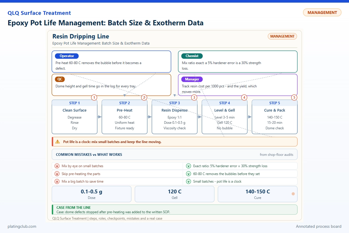
RESIN DRIPPING · SENIOR TECHNICIAN FIELD GUIDE
Epoxy Pot Life Management: Batch Size & Exotherm Data
For decorative resin dripping on plated zinc-alloy bag hardware, the useful processing window ends when the resin stops filling the recess correctly, not when the mixing cup becomes solid. Senior technicians must connect batch mass, container geometry, temperature, dispensing delay and cured quality. A resin that passes a fresh-mix trial can still produce bubbles, uneven domes or weak edges at the end of a production batch.
This guide separates published laboratory values from proposed workshop controls. No QLQ customer trial, salt-spray result or measured mass-versus-temperature curve is available for this specific application. The commercial system below is a traceable reference, not an approved QLQ formulation or an automatic qualification for adhesion to electroplated hardware.
1. Define the dispensing limit before increasing batch size
Pot life describes a specified quantity under specified test conditions. It is not interchangeable with thin-film working time, tack-free time or full cure. Container dimensions and heat loss change the result. A useful plant endpoint combines three observations: acceptable dispense mass, acceptable flow into the recess, and an acceptable internal resin temperature. See the manufacturer's explanation of pot life and cure stages.
Start the batch timer at first resin-hardener contact. Include mixing, transfer, any approved degassing, queue time and nozzle residence. Record the first and last acceptable parts against elapsed time. Never reset the timer after transfer. A fresh batch added to an old cup inherits aged material and makes its process history untraceable.
Use an immersed probe in a dedicated sacrificial process-control sample with matched geometry; infrared readings alone can miss a hotter core. Log actual resin temperature rather than room temperature alone. During qualification, use continuous logging or a sufficiently short interval to capture acceleration; ordinary production checks cannot substitute for establishing the thermal envelope.
2. Working Data & Formula Notes
A complete purchased two-component system avoids guessing the hardener's active-hydrogen equivalent weight. The reference is Entropy CCR resin with either CCF fast or CCS slow hardener. The manufacturer's technical data sheet specifies 100:43 and 100:42 resin-to-hardener mass ratios respectively. These are alternatives, not a permissible adjustment range for one hardener.
| Component | Range | Typical | Function | Replenishment |
|---|---|---|---|---|
| CCR supplied resin, Part A | 100, fixed reference basis | 100.00 | Epoxy-bearing supplied resin package | Fresh weighed charge only; do not top up mixed resin |
| CCF supplied hardener, Part B, fast option | 43, fixed supplier ratio; not adjustable | 43.00 if CCF is selected | Cures the resin using the fast package | Weigh separately for every batch; exclude CCS |
| CCS supplied hardener, Part B, slow alternative | 42, fixed supplier ratio; not adjustable | 42.00 if CCS is selected | Alternative slower-curing package | Weigh separately for every batch; exclude CCF |
| Added solvent, pigment, filler or accelerator | 0 in this reference | 0.00 | Maintains the published unmodified-system basis | None; any additive requires supplier approval and requalification |
For a 100 g total CCF trial, weigh 69.93 g resin and 30.07 g hardener. For CCS, weigh 70.42 g and 29.58 g. Calculate resin mass as total mass divided by 1 plus the hardener/resin ratio. These arithmetic conversions do not authorize a particular cup size or production batch mass. Do not substitute a volume ratio when using scales.
Never reduce hardener to extend pot life or increase it to recover a cold cure. Changing stoichiometry changes the network, not merely the clock. For pigmented work, determine whether the supplier's ratio applies to neat resin or a pre-formulated colored Part A. Pigment-carrier compatibility, dispersion and optical appearance need independent approval.
3. Published test comparison and the missing exotherm evidence
| System / specimen | Mass ratio A:B | Pot life | Mixed viscosity | Hardness | Test condition |
|---|---|---|---|---|---|
| CCR/CCF, fast laboratory reference | 100:43 | 90 min | 370 mPa·s | Shore D 70–80 | Pot life and viscosity: 25°C. Hardness specimen geometry and conditioning are not specified in the cited TDS. |
| CCR/CCS, slow laboratory reference | 100:42 | 360 min | 270 mPa·s | Shore D 70–80 | Pot life and viscosity: 25°C. Pot-life batch mass and cup geometry are not specified in the cited TDS. |
Values above come from the linked CCR TDS. It recommends seven days at 25°C for full cure and recommends post-curing. The website's introductory pot-life temperature wording differs from its processing table; use the identified TDS basis and request clarification before writing a production specification. Neither document supplies a validated pot-life value for your particular dispensing reservoir.
Hardness is not proof of metal adhesion, and Shore D must not be read directly on a thin dome backed by metal. Use a suitable cured witness specimen and a documented test method. Film thickness and salt-spray performance on plated zinc alloy remain unconfirmed; no numerical corrosion claim can be extracted from these bulk-resin results.
| Trial | Test condition | Thermal / flow data | Coupon comparison | Result status |
|---|---|---|---|---|
| A: minimum practical batch | CCF, 25°C; approved shallow cup; proposed 50 g starting trial | Log core temperature, time and viscosity until dispensing cutoff | Start/end coupons; proposed dome thickness 0.50 ± 0.10 mm | Not measured |
| B: next mass step | Same chemistry, temperature, cup family and workpiece; mass increase only after A passes | Compare peak temperature and usable time with A | Same recess geometry, plating lot and cure schedule | Not measured |
| C: hot-shift challenge | Previously approved mass; highest expected material temperature, within supplier limits | Check acceleration and last-part flow | Matched cured witness hardness and edge adhesion | Not measured |
| D: slow-system comparison | CCS at its specified ratio; repeat the qualified geometry | Establish a new thermal envelope, not a transferred CCF limit | Compare appearance after its own complete cure | Not measured |
Run at least three independent batches per selected condition. Preserve probe position, fill depth and ambient airflow in the records. Photograph coupon edges before and after the customer-specified corrosion exposure; record blistering, discoloration and adhesion separately. Do not improvise a salt-spray duration and present it as a customer acceptance standard.
4. Normal bands versus intervention thresholds
The following are provisional engineering controls for initial shallow-dome qualification, not universal epoxy properties. Replace them with approved limits from measured capability and supplier instructions. “Danger” here includes quality loss and process instability; it is not a certified thermal-safety boundary. Earlier supplier restrictions always take precedence.
| Parameter | Proposed normal band | Danger / intervention threshold | Required response |
|---|---|---|---|
| Starting material temperature | 23–27°C around a 25°C trial basis | Outside the qualified temperature band | Hold and condition unopened components; reassess viscosity |
| Hardener mass-ratio error | Within ±1% relative to the specified hardener charge | Beyond ±1%, or uncertainty too large to verify it | Quarantine; check scale resolution and metering |
| Core rise above starting temperature | Less than 5°C during proposed dispensing window | 5°C rise or accelerating temperature | Stop dispensing; follow the resin-specific thermal response |
| Viscosity relative to fresh mix | 1.00–1.25 times baseline at matched test temperature | Above 1.25 times baseline or incomplete recess filling | Discard aged process material through the approved route |
| Batch elapsed time | At or below 50% of locally measured usable time | Beyond the qualified dispensing cutoff | Stop; do not rely on published pot life alone |
| Dispense mass per part | Within ±5% of qualified target | Beyond ±5%, stringing or overflow | Hold parts since last passing check |
| Dome thickness, example design | 0.40–0.60 mm for a 0.50 mm target | Outside drawing tolerance or uncovered recess edges | Correct dispense setup; recheck actual cured geometry |
Watch trends, not isolated readings. A temperature rise accompanied by increasing dispense pressure is more significant than either signal alone. Calculate viscosity ratios at the same measurement temperature: warm resin may temporarily appear thinner even while its cure advances.
For planning, batch mass must satisfy both the validated thermal limit and consumption capacity. If dispensing consumes 6 g/min, the approved window is 12 minutes, preparation takes 3 minutes and contingency takes 2 minutes, consumption supports only 42 g. This is an illustrative calculation, not measured exotherm data or authorization to mix 42 g in any container.
5. Two reference-based troubleshooting cases
Case A: a larger cup causes premature thickening
Scenario: the operator scales up a previously acceptable mix to reduce changeovers. The final parts show stringing while the first parts look normal. Test batch mass and fill depth before blaming the nozzle. Return to the qualified small batch, reproduce the delay with a monitored control sample, then increase only one variable at a time. This is a diagnostic scenario, not a reported customer outcome.
Its mechanism is supported by WEST SYSTEM's uncontrolled-cure guidance: retained reaction heat can accelerate cure, and spreading mixed resin into a suitable shallow container improves heat dissipation. A hot or smoking vessel must be handled under the site's emergency procedure, not by ad hoc decanting.
Case B: soft edges persist despite stable cup temperature
Scenario: the monitored batch stays inside its qualified thermal window, but some domes remain tacky or detach at the metal interface. Compare independent ratio checks, mixing uniformity, surface cleanliness and actual cure history. Inspect the separation plane: resin-to-metal failure differs from plating-to-zinc failure. A longer pot-life hardener cannot repair an unstable substrate.
The QLQ local knowledge-base note on zinc-alloy plating defects identifies trapped contamination, moisture and poor pretreatment as sources of blistering and peeling. That substrate diagnosis is relevant; its plating or impregnation recipes are not decorative epoxy-dripping formulations. Preserve unaffected and failed samples before changing cleaning or curing conditions.
6. Engineer Notes
- Verify scales with check weights spanning both component charges. Record actual masses; a nominal pump setting alone is not evidence of ratio.
- Mix with a repeatable tool and qualified duration, scraping walls and base. Transfer into a clean cup and remix where the supplier permits this method.
- Label each vessel with chemistry, lot numbers, contact time, mass and discard deadline. Keep old and fresh resin physically separated.
- Measure reservoir and hose residence time during stops. If restart material exceeds the qualified age, replace it and quarantine questionable parts.
- Check first, middle and last parts against a retained visual reference. Include recess corners, bubbles, edge wetting and dispense weight.
- Prepare a monitored, noncombustible isolation area. Do not seal reacting waste, use sawdust for hardener spills, or ask operators to carry a smoking cup.
- Approve chemistry changes through new trials. CCR product guidance restricts CCF to small-volume applications; those casting restrictions are not validated limits for a dispensing reservoir.
7. Shift Checks
| Shift stage | Check item | Frequency | Acceptance standard | Record |
|---|---|---|---|---|
| Before shift | Material identity, temperature, scale and dry fixtures | Every startup and lot change | Approved chemistry; qualified band; verification passes | Lot IDs, temperatures, check-weight result |
| Before shift | First mix and first-part dispensing | First batch | Correct ratio; target fill without overflow | Masses, timer start, sample photograph |
| During shift | Core trend, age and remaining mass | Continuous temperature monitoring; review each batch | Inside approved thermal and time limits | Temperature trace and discard time |
| During shift | Dispense mass and recess appearance | Start/middle/end of batch and after interruptions | Qualified mass tolerance; no bubbles or exposed corners | Part IDs, weights, hold boundary |
| After shift | Waste isolation and equipment shutdown | Every shutdown | No reacting material in closed waste; approved cleaning complete | Waste log and shutdown sign-off |
| After shift | Cure records and witness-sample review | Each lot at its specified cure age | Drawing, adhesion and approved hardness criteria met | Cure history, laboratory results, release decision |
8. Technician-to-AI FAQ
These are practical example prompts, not quotations from recorded customer conversations.
“AI, my epoxy has a 90-minute pot life. Why does our larger production cup thicken much sooner?”
The published test does not reproduce your mass, geometry or thermal history. Compare starting temperature, fill depth and elapsed time from first contact. Establish a local usable-time curve with temperature logging and start/end coupons; do not scale mass from the published minutes.
“AI, can I add fresh resin or solvent to recover a batch that is starting to string?”
No recovery addition is qualified here. Stop, hold suspect parts and follow the approved waste procedure. New material obscures age and ratio; solvent changes the formulation. Investigate batch size, mixing delay and nozzle residence before restarting with a traceable fresh mix.
“AI, the dome is hard but peels after exposure. Does that prove the hardener ratio was wrong?”
No. Bulk hardness cannot identify the failure interface. Check cured witness samples, contamination, plating adhesion, edge coverage and the agreed exposure method. Compare early and late coupons, then locate the fracture plane before selecting a chemistry or pretreatment correction.
What Would You Like to Solve?
Send the resin TDS, component ratio, batch mass, container dimensions, temperature trace, dispensing rate and photographs of early and late parts to [email protected]. Include the plated substrate, recess drawing and acceptance criteria. These details help distinguish heat retention from mixing, surface preparation and cure problems.
For coordination with upstream cleaning, plating and production layout, review surface-treatment line equipment, chemicals and engineering support. Epoxy compatibility of any dispensing equipment must be confirmed separately; a silicone or PVC machine listing does not establish epoxy suitability.