
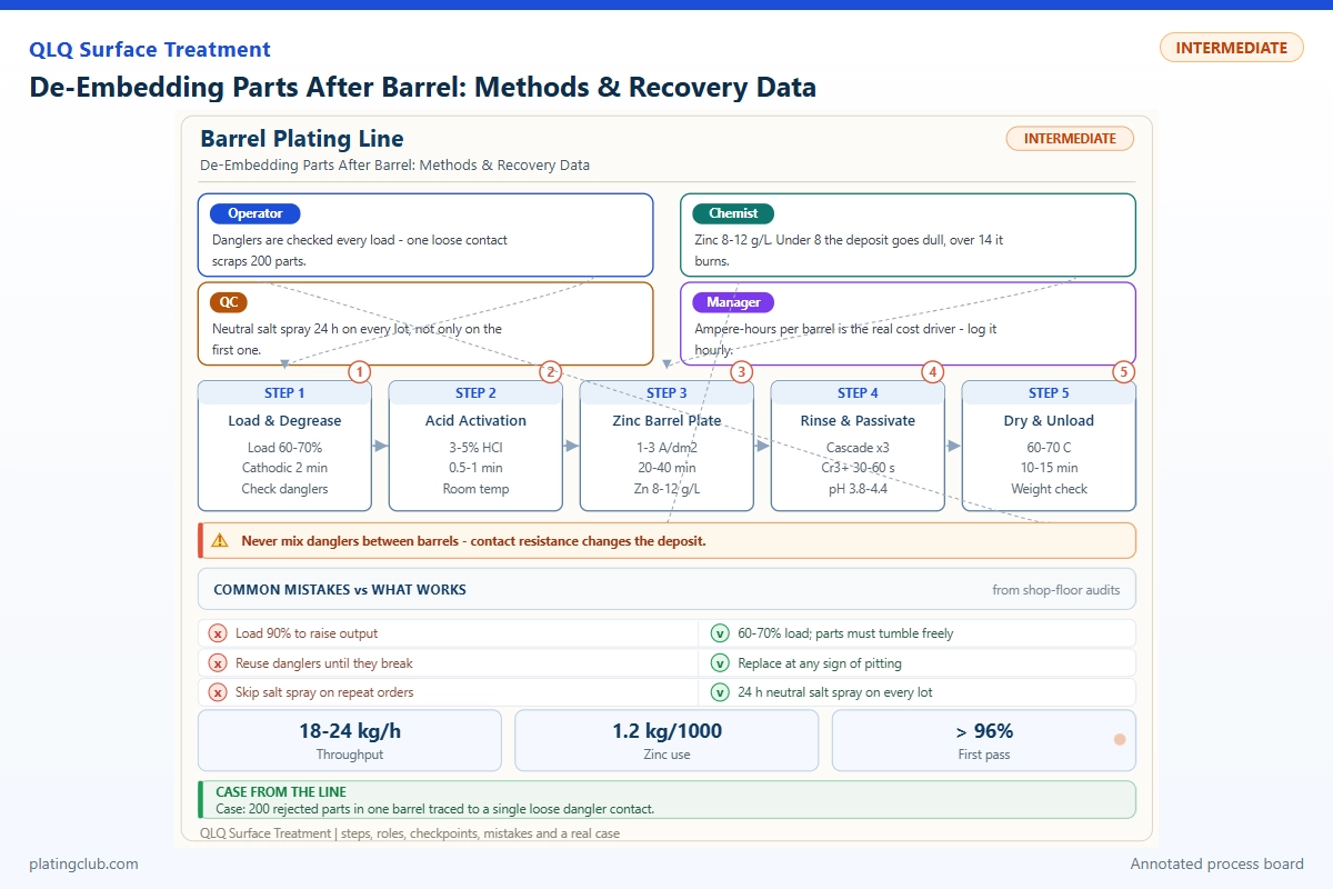
BARREL PLATING / JUNIOR TECHNICIAN / RECOVERY WORK INSTRUCTION
De-Embedding Parts After Barrel: Methods & Recovery Data
Two plated parts leave the barrel locked together. Separating them is only half the job: the hidden contact area may be thin, bare, scratched, or contaminated. A successful recovery produces an individually free component that still meets its coating and dimensional requirements, not simply a loose component.
This guide treats “de-embedding” as releasing nested, interlocked, or wedged parts after barrel electroplating. It does not describe removing polishing abrasive from a surface. The intended reader already has practical finishing experience but needs a repeatable diagnosis, controlled recovery trial, and defensible release record.
1. Identify the lock before applying force
Hold the affected lot and preserve its traveler. Record substrate, coating stack, barrel identification, load mass, speed, plating time, and the stage where sticking was first noticed. Photograph intact clusters beside a scale. Compare them with unplated components: parts that already nest mechanically will not become safe to barrel-plate merely by changing a brightener.
| Observed mechanism | Useful evidence | First controlled action | Stop condition |
|---|---|---|---|
| Flat faces or shallow cups nest | Broad matching contact patches; pairs separate without bent edges | Wet, supported separation along the available clearance | Bare patch or coating lift beneath the overlap |
| Hooks or spring features interlock | Geometrical engagement visible under magnification | Reverse the insertion path while supporting both pieces | Permanent opening, deformation, or cracking |
| Small part wedges inside another | Mixed dimensions or a tapered cavity | Isolate the combination; inspect clearances and burrs | Release requires uncontrolled leverage |
| Suspected metal bridge | Continuous deposited metal across a contact edge | Refer to the process engineer for rework disposition | Do not fracture the bridge and classify the surface as sound |
Never reach into a rotating barrel. Isolate motion and electrical energy under the plant procedure before opening or servicing equipment. Keep rinse water and nickel-bearing residues in the approved collection system. Use the applicable SDS and site exposure controls, including suitable gloves and eye protection.
2. Choose the least damaging recovery method
Supported manual separation
Work over a lined tray with clean, approved polymer tools. Support the receiving part and move the inserted part back along its entry path. Do not twist a thin hook sideways or scrape a decorative face with a screwdriver. Keep recovered, questionable, and rejected pieces in separately labeled trays. Inspect the formerly hidden surface immediately; otherwise the original contact mark can disappear into a mixed pile.
Water-assisted release
For loosely nested surfaces, try clean process-compatible water in a small recovery basket. Gentle movement can help replace trapped liquid and allow sliding. Water is not a stripping agent and cannot restore a coating that was never deposited. Rinse, dry, and inspect through the approved sequence; an uncontrolled soak can introduce stains or delay required downstream treatment.
Low-energy basket movement or ultrasonic trial
Use a sacrificial, traceable subset before any powered method. A perforated basket can retain parts while allowing gentle movement. Ultrasound is an engineering-approved option only when the coating, substrate, assembly, and equipment are compatible. Record actual power setting, basket position, temperature, and duration. Published use of ultrasound to prevent nesting during specialized plating does not prove that a post-plating ultrasonic cleaner will safely release your product.
Rework or route change
Send damaged, bridged, or undercoated pieces to authorized rework assessment. Do not improvise acid, alkali, solvent, or electro-stripping treatment. Zinc-alloy hardware can be attacked if its protective layer is breached, and extra acid exposure may create additional risks for susceptible steel components. Any hydrogen-embrittlement treatment requirement remains governed by the drawing and qualified process.
3. Working formula: the plating bath, not a release chemical
The following is an additive-free Watts nickel reference composition. The European Commission surface-treatment reference document gives industrial concentration ranges of 240–375 g/L nickel sulfate, 35–60 g/L nickel chloride, and 30–45 g/L boric acid. The typical targets below are selected trial values within those ranges, not a QLQ proprietary recipe. Confirm commercial salt hydration, assay, and the supplier's operating sheet before calculating additions.
| Component | Range | Typical | Function | Replenishment |
|---|---|---|---|---|
| Nickel sulfate, specified commercial hydrate | 240–375 g/L | 300 g/L | Principal nickel source | Laboratory analysis; balance soluble-anode contribution and drag-out before adding |
| Nickel chloride, specified commercial hydrate | 35–60 g/L | 45 g/L | Supports conductivity and nickel-anode dissolution | Analyze chloride; add only the calculated deficit |
| Boric acid | 30–45 g/L | 40 g/L | Supports control near the cathode surface | Analyze; dissolve through the approved addition procedure |
| Deionized water | Balance to working volume | Final working volume | Solvent and concentration control | Restore verified level before sampling |
| Brightener, carrier, and wetting agent | None in this reference bath | 0 added | Not part of this additive-free formulation | For a production bright bath, use its complete supplier recipe instead |
This complete base formulation is not suitable for every decorative barrel specification. It is not a direct-to-zinc-alloy process: substrate preparation and any required strike or undercoat must be qualified separately. Source: European Commission, Surface Treatment of Metals and Plastics, section 2.5.2.1.
For an approved component addition, mass in kilograms = concentration deficit in g/L × verified bath volume in liters ÷ 1,000, adjusted for assay and chemical basis. For example, a 5 g/L deficit in a 500 L bath corresponds to 2.5 kg on that stated basis. This calculation does not authorize an addition: first check water level, sample validity, and the laboratory instruction.
4. Trend bands and intervention thresholds
The numeric bands below are proposed trial-control limits, not universal damage thresholds or published production settings. The responsible engineer must validate them for the actual part and equipment. Supplier limits and the approved traveler take precedence. Repeated movement toward a boundary deserves investigation even before an alarm occurs.
| Parameter | Proposed normal fluctuation band | Danger / hold threshold for this trial | Action |
|---|---|---|---|
| Recovery-water temperature | 20–30°C | Outside 15–35°C | Hold; check compatibility before restoring temperature |
| Powered recovery duration | 30–60 seconds per inspection interval | More than 120 seconds cumulative without approval | Stop and inspect rather than extending blindly |
| Barrel load versus qualified mass | 95–100% of approved target | Above 100%, or below qualified minimum | Do not run outside the qualified loading window |
| Barrel speed versus approved setting | Within ±5% | Deviation exceeding ±10% | Check drive and actual rotation before processing |
| Recovery-basket fill depth | One loose layer for initial screening | Multiple compacted layers | Split the trial to expose and inspect every part |
| Free control-piece damage, sample of 30 | 0 visibly damaged | 1 or more new scratches, bends, or blisters | Stop the method and hold its treated population |
| Former contact-zone thickness | At or above drawing minimum | Any confirmed value below minimum | Segregate for approved rework assessment |
A speed increase is not automatically an improvement: separation can rise while scratching and deformation also rise. Keep load, recovery energy, and exposure time in the same log so the shift can see their relationship.
5. Recovery experiments: measure released quality, not just separation
No verified QLQ de-embedding experiment or numerical recovery dataset was available in the searched knowledge base. The table is therefore a ready-to-run experimental record, with planned sample sizes and conditions, not fabricated measured results. Replace “Pending” with traceable readings before claiming performance. Use actual nested parts; flat witness coupons alone cannot reproduce their hidden contact zones.
| Trial / control | Test condition | Separated / tested | Contact-zone thickness, µm | New damage count | Corrosion result |
|---|---|---|---|---|---|
| C0: free-part control | 30 already-free pieces; approved rinse/dry only; same coating lot | Not applicable / 30 planned | Pending: individual readings and minimum | Pending | Pending: buyer-specified method and duration |
| M1: manual release | 30 nested pairs; supported polymer-tool separation; inspect every recovered piece | Pending / 60 planned pieces | Pending: formerly shielded zone | Pending | Pending: matched finish and test conditions |
| W1: water-assisted release | 30 nested pairs; 20–30°C compatible water; inspect after 30 seconds; maximum 60 seconds for initial trial | Pending / 60 planned pieces | Pending: formerly shielded zone | Pending | Pending: matched finish and test conditions |
| U1: optional ultrasonic trial | Engineer-approved setting; record power and basket position; inspect at 30 seconds before continuation | Pending / 60 planned pieces | Pending: formerly shielded zone | Pending | Pending: matched finish and test conditions |
Use an appropriate calibrated thickness method. A curved recess may not be accessible to an XRF measurement; ask the laboratory whether sectioning or another qualified method is needed. Identify the measured layer when copper, nickel, and a final finish are stacked. Do not report total thickness as nickel thickness.
Record corrosion-test method, exposure duration, coating stack, conditioning, and acceptance criterion. Salt-spray hours do not translate directly into service life. If hardness is required, specify the method, load, and coating-thickness suitability; a substrate-dominated reading cannot establish deposit hardness.
Separation yield = free pieces ÷ treated pieces × 100. Accepted recovery yield = specification-compliant pieces ÷ treated pieces × 100. Arithmetic example only: 48 free pieces from 60 gives 80% separation; if only 42 pass inspection, accepted recovery is 70%. These numbers are teaching calculations, not test observations. Repeat the preferred method on independent lots before approving routine use.
6. Two field references that explain the problem
Interlocking and flat hardware
Gatto Industrial Platers identifies open springs, hooks, and U-shaped components as tangling risks, while flat or nestable parts can stick and develop coverage defects. Its guidance favors considering rack processing for such geometry. This is a published process example, not a quantified QLQ recovery trial. For bag-hardware workshops, the practical lesson is to check the contact geometry before repeatedly treating the same locked pairs. Reference: Part Shape Matters.
Small aerospace contacts with deep recesses
Electro-Spec describes contacts that showed nesting, uneven thickness, and poor internal coverage in earlier barrel and vibratory trials. Its alternative spouted-bed electrode process used refreshed electrolyte and ultrasonic component movement to maintain separation. The reported outcome was satisfactory coverage; numerical thickness and recovery percentages were not disclosed. This supports considering a different process for difficult geometry, not copying an unspecified ultrasonic setting into a recovery tank. Reference: Aerospace Plating with Critical Requirements.
7. Engineer Notes
- Retain three intact clusters before recovery; photograph the engagement and mark their original lot.
- Inspect an unplated pair for burrs and interference; record whether it locks without any deposit.
- Separate different sizes before the next trial; document which small-part/large-part combination caused wedging.
- Verify barrel mass and actual rotation against the traveler; change only one approved variable per comparison.
- Pass already-free controls through the proposed recovery method to reveal damage caused by recovery itself.
- Inspect every formerly hidden contact patch in the trial; send questionable thickness locations to the laboratory.
- Retain the reject tray until the engineer signs disposition; never return unreleased pieces to finished stock.
8. Shift Checks
| Shift stage | Check item | Frequency | Acceptance standard | Record |
|---|---|---|---|---|
| Before shift | Isolation procedure, tools, trays, instructions | Before recovery starts | Approved procedure available; clean tools; traceable segregation | Operator checklist and instruction revision |
| Before shift | Instrument verification and bath status | Each shift; laboratory schedule for chemistry | Verification current; production bath within approved limits | Instrument ID and bath-analysis reference |
| During shift | Barrel mass, speed, mixed geometry | Every load | Qualified traveler settings; no unapproved mixed sizes | Load ticket and barrel ID |
| During shift | Recovery temperature, exposure, fresh damage | Every trial and inspection interval | Within signed trial limits; zero new control damage | Trial sheet and timer readings |
| During shift | Hidden-zone coating and dimensions | Every recovered trial piece; laboratory sampling as approved | Drawing and finish specification satisfied | Inspection map and readings |
| After shift | Count reconciliation and disposition | Each held lot | Accepted + held + rejected equals treated count | Signed lot disposition |
| After shift | Waste collection and handover | End of shift | No uncontrolled discharge; all unresolved lots clearly held | Waste log and next-shift handover |
9. Technician questions to ask AI
These are example technician prompts, not claimed transcripts from customers. Give AI the approved procedure and measured evidence; let the responsible engineer authorize changes.
“My parts separate in water, but there is a pale patch underneath. Can I ship them?”
Not on separation alone. Hold the pieces, identify whether the patch is stain, abrasion, or insufficient coverage, and measure the relevant layer at the former overlap using an appropriate method. Release requires the specified appearance, thickness, and dimensional checks.
“Should I increase barrel speed to stop the hooks tangling?”
First check geometry, loading, and the approved speed window. Higher speed can increase collision damage without eliminating interlocking. Request a controlled comparison; recurring geometry-driven failures may require rack plating or a qualified alternative.
“The ultrasonic cleaner frees more pieces. What data should I show my supervisor?”
Show accepted recovery yield alongside separation yield, new damage on free controls, hidden-zone thickness, dimensional results, and the exact exposure conditions. Include independent repeat lots and any specified corrosion testing. A higher loose-part count alone is insufficient evidence.
10. What Would You Like to Solve?
Send part photographs, substrate, coating stack, cluster examples, barrel settings, and actual inspection results to [email protected]. QLQ can review the process context and help define the information needed for an engineering assessment. For the broader line context, see surface-treatment equipment, chemicals, and process support.
Local knowledge-base basis: the note titled Rack and Barrel Plating Equipment (English translation; original filename, URL-encoded: %E6%8C%82%E9%95%80%E4%B8%8E%E6%BB%9A%E9%95%80%E8%AE%BE%E5%A4%87.md) in the QLQ Obsidian Vault, specifically its barrel-loading, collision, deformation, and parameter-control guidance. No customer recovery percentage, unverified equipment setting, or unpublished experimental result is attributed to QLQ here.