
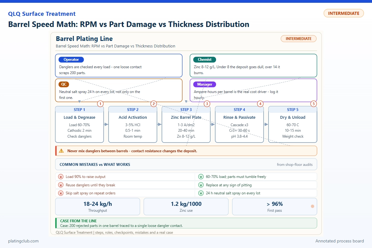
Barrel Speed Math: RPM vs Part Damage vs Thickness Distribution
Increasing barrel speed can improve turnover, but it does not automatically increase useful plating. The right speed keeps parts exchanging positions and making electrical contact without damaging edges, tangling thin components, or interrupting current. For a junior technician, the practical objective is repeatable minimum thickness with acceptable appearance, not the highest RPM the drive can deliver.
QLQ's barrel-plating knowledge note lists 8–15 rpm, 30–50% volumetric loading, and 0.5–3 A/dm² as general references for small hardware. These are not a validated recipe for every barrel or finish. Use the approved part-specific route first; treat the calculations below as tools for investigating changes, never as permission to override a process sheet.
1. What Speed Changes Inside the Barrel
Slow rotation may leave the same pieces buried in the load while exposed pieces receive more current. Faster rotation may improve exchange, but repeated collisions and unstable contact can erase that benefit. Geometry matters: a compact rounded part and a thin pull with an open loop behave differently at identical speed.
Watch for sliding as one packed mass, persistent nesting, or parts climbing and dropping sharply. Do not open a moving barrel or defeat guards to observe the load. Use approved viewing arrangements or inspect after isolation. A smooth motor sound does not prove that the barrel is turning correctly under load.
| Observed problem | Possible explanation | First check |
|---|---|---|
| Thin recesses, satisfactory exposed faces | Poor exchange, nesting, or limited solution access | Loading volume, hole blockage, and part geometry |
| Dents on edges and decorative faces | Collision damage from speed, loading, or transfers | Compare incoming parts with samples taken before drying |
| Patchy or bare areas | Intermittent contact or preparation failure | Conductive pins, danglers, cleaning, and activation records |
| Roughness on many surfaces | Particles or bath instability rather than RPM alone | Filtration, analytical results, and anode-bag condition |
2. Working Data & Formula Notes
Use the barrel's actual internal diameter, not the motor pulley diameter. For a circular approximation, surface travel speed is v = πDN/60, where D is diameter in metres and N is rpm. A 0.30 m barrel at 8 rpm gives 0.126 m/s; at 15 rpm it gives 0.236 m/s. Polygonal barrels and slipping loads do not move exactly like this ideal surface.
A useful comparison is Fr = ω²R/g, where ω = 2πN/60, R = D/2, and g = 9.81 m/s². This dimensionless ratio compares rotational acceleration with gravity. It is not a damage predictor or a machine safety limit. At the same diameter, increasing from 8 to 15 rpm multiplies Fr by 3.52, even though RPM rises only 1.875 times.
| RPM | Surface speed | Fr | Turns in 30 min | Test condition |
|---|---|---|---|---|
| 8 | 0.126 m/s | 0.0107 | 240 | Ideal 0.30 m diameter; fixed duration |
| 11 | 0.173 m/s | 0.0203 | 330 | Same geometry; no load-slip model |
| 15 | 0.236 m/s | 0.0377 | 450 | Same geometry; no impact-energy measurement |
Thickness also depends on charge. For nickel, Faraday's law gives d = 12.29ηjt in micrometres, with efficiency η as a fraction, j in A/dm², and t in hours. This follows from nickel's molar mass, divalent deposition, Faraday's constant, and density. At 1 A/dm², 0.5 hour, and an assumed 95% efficiency, the area-average estimate is 5.84 µm.
That estimate cannot certify a recess. The current density must use total actual part area; do not confuse tank current, barrel current, and instantaneous current on exposed parts. Record ampere-hours, since identical timer settings do not ensure equal charge when current fluctuates.
3. A Defined Nickel Bath for Controlled Trials
The table defines an additive-free Watts reference bath, not a proprietary QLQ bright-nickel formula. EPA's nickel-plating report supports the concentration ranges below. Nickel salts are specified by hydrate; convert by molecular weight if the purchased material differs. A production bright finish requires the supplier's complete additive package and control instructions.
| Component | Range | Typical | Function | Replenishment |
|---|---|---|---|---|
| Nickel sulfate hexahydrate, NiSO₄·6H₂O | 195–262 g/L | 240 g/L | Main nickel-ion source | Analyze nickel; account for soluble-anode supply and drag-out before adding salt |
| Nickel chloride hexahydrate, NiCl₂·6H₂O | 45–90 g/L | 60 g/L | Supports anode dissolution and conductivity | Analyze chloride; use an approved calculated addition |
| Boric acid, H₃BO₃ | 37.5–49 g/L | 40 g/L | Buffers the cathode environment | Analyze; dissolve additions by the approved method, avoiding undissolved crystals |
| Deionized water | Balance to final volume | To 1 L | Solvent and volume control | Restore the marked working level before comparing analyses |
| Brightener, leveler, wetting agent | None in this base reference | 0 | Excluded to define the reference chemistry completely | Do not introduce during the RPM comparison; production packages require separate validation |
For this reference trial, propose pH 3.5–4.0 and 40–45°C, subject to engineering approval. QLQ's general temperature reference is not interchangeable with a chemistry supplier's specified window. Additive-free nickel is not expected to have a mirror-bright appearance. Neither speed nor an unapproved brightener addition should be used to disguise that difference.
Nickel compounds require the applicable SDS, trained handling, extraction, and controlled wastewater management. Junior technicians should not make up or correct baths independently. All chemical additions require the approved procedure and authorization.
4. Experimental Batch Comparison: What to Measure
No verified QLQ RPM-versus-thickness experimental dataset was available in the searched notes. The following is an experimental recording table, with pending measurements deliberately left unclaimed. Populate it with shop results rather than copying invented coating thickness, hardness, or salt-spray performance.
Use one part design and incoming lot. Keep loading, preparation, chemistry, current setting, duration, and transfers unchanged. Subject to approval, compare 8, 11, and 15 rpm at 40% volumetric loading. Repeat each setting for three batches, randomize the order where practical, and log bath conditions so time-related drift is visible.
| Batch group | Test condition | Thickness data | Damage data | Decision |
|---|---|---|---|---|
| A1–A3 | 8 rpm; 40% fill; 1 A/dm² nominal; 30 min; approved nickel route | Pending: face/recess min, mean, max, µm | Pending: damaged count / 100 inspected | Hold for measurement |
| B1–B3 | 11 rpm; otherwise same; record actual ampere-hours | Pending: identical measurement locations | Pending: same defect classification | Compare minimum, not mean alone |
| C1–C3 | 15 rpm; otherwise same; inspect for deformation | Pending: identical measurement locations | Pending: scratches, dents, bent features | Stop early if unacceptable damage appears |
Sample 30 parts per batch across the discharge sequence and measure one designated face and one designated recess per part where the instrument geometry permits. Use calibrated, layer-appropriate XRF; inaccessible recesses may require cross-sections. A loose flat coupon is not a substitute for the real component's shielding and contact behavior.
Calculate thickness spread as maximum minus minimum, and damage rate as damaged pieces divided by inspected pieces times 100%. If hardness or corrosion resistance is specified, test matched specimens using the customer-approved method and complete finish stack. Do not infer salt-spray hours from nickel thickness alone. Release requires measured conformance, not a favourable average or a calculated deposit estimate.
5. Normal Bands and Action Thresholds
These are proposed control-plan limits for the defined trial, not universal chemical failure thresholds. The normal band is narrower than some published reference ranges. Leaving it triggers investigation; crossing an action limit triggers the approved hold procedure. Product drawings and supplier limits take precedence.
| Parameter | Normal fluctuation band | Danger / action threshold | Response |
|---|---|---|---|
| Actual speed at 11 rpm setting | 10.5–11.5 rpm | Outside band; stopped or surging rotation | Verify tachometer and drive before continuing |
| Volumetric fill | 38–42% for this trial | Outside band invalidates comparison; >50% exceeds QLQ reference | Correct loading using the qualified method |
| Nominal current density | 0.95–1.05 A/dm² | Outside band; sustained current interruptions | Check area calculation and contact system |
| Bath temperature | 40–45°C | <40 or >45°C for this trial | Hold comparison; investigate heater and sensor |
| Bath pH | 3.5–4.0 | <3.3 or >4.2; intermediate drift requires review | Verify calibrated measurement; authorize correction |
| Nickel sulfate hexahydrate equivalent | 230–250 g/L | <195 or >262 g/L reference boundary | Check analysis, water level, and anodes |
| Nickel chloride hexahydrate equivalent | 55–65 g/L | <45 or >90 g/L reference boundary | Review chloride balance and replenishment |
| Boric acid | 38–42 g/L | <37.5 or >49 g/L reference boundary | Confirm analysis and inspect for crystallization |
6. Two Knowledge-Base Troubleshooting Cases
Case A: Small pulls show collision marks
QLQ's barrel-plating note identifies excessive speed as a cause of part damage. Apply that documented failure mode by comparing incoming pulls, post-plating samples, and post-drying samples. If marks first appear during plating, restore the qualified speed and loading, then test one change at a time. If marks appear only after drying, investigate the dryer and transfers. No customer identity or numerical improvement is claimed here.
Case B: Small components have partial missing plating
The same note identifies poor conductivity as a cause of partial missing plating and calls for cleaning conductive pins. Isolate the equipment, inspect contacts and connections, and restore the approved contact condition before an RPM trial. Verify coverage alongside cleaning and activation. The diagnostic endpoint is measured coverage with stable current; increasing speed without repairing contact may simply add collisions.
7. Engineer Notes
- Measure loaded barrel RPM with an approved non-contact method; do not equate inverter frequency with shaft speed.
- Record both load mass and settled volume. A kilogram value alone cannot reproduce fill when part geometry changes.
- Label incoming, post-plating, and post-drying samples before inspection so handling damage is not blamed on the bath.
- Change only one approved factor per comparison; record every chemistry correction that interrupts the trial.
- Photograph fixed thickness locations and use them on every sampled part. Keep instrument calibration evidence with results.
- Log actual current and ampere-hours. Investigate interruptions before compensating with longer time or higher current.
- Stop and isolate for abnormal noise, jammed rotation, leaking closures, or visibly deformed parts; never reach into running equipment.
8. Shift Checks
| Shift stage | Check item | Frequency | Acceptance criterion | Record |
|---|---|---|---|---|
| Before shift | Guards, closure, contacts, perforations | Before first load; inspect isolated | Secure, clean, unobstructed; no unresolved fault | Equipment checklist and fault reference |
| Before shift | pH, temperature, approved analysis | Start-up and after correction | Within authorized bath window | Readings, analysis date, operator |
| During shift | Fill, mass, actual RPM | Every load; RPM after setting changes | Approved loading and speed band | Batch ID and measured values |
| During shift | Current, time, ampere-hours | Each batch; review interruptions immediately | Authorized route; no unexplained loss of contact | Rectifier log and deviations |
| During shift | Thickness and damage | Trial: every batch; production: control plan | Drawing minimum and agreed appearance standard | Locations, instrument, counts, disposition |
| After shift | Load reconciliation and maintenance needs | At handover | All batches traceable; held stock clearly identified | Handover sheet and corrective-action owner |
9. Technician Questions to Ask AI
These are suggested technician prompts, not claimed verbatim customer correspondence.
“If I increase barrel speed from 8 to 15 rpm, will my nickel thickness increase?”
Not necessarily. Speed changes exchange and contact, whereas deposited mass primarily follows charge and efficiency. Compare actual ampere-hours, minimum recess thickness, and damage counts; a higher mean with worse recess coverage is not an improvement.
“My parts are scratched but the average thickness passes. What should I check first?”
Locate the first stage where scratches appear using incoming, post-plating, and post-drying samples. Then inspect loading, geometry, speed, and transfers for that stage. Keep scratched stock on hold even if its average thickness meets the drawing.
“Can I fix bare areas by turning the barrel faster?”
Check electrical contacts and preparation first. Faster movement cannot repair a dirty conductive pin or inadequate activation. Restore the approved conditions, verify coverage, and only then conduct a controlled speed comparison.
What Would You Like to Solve?
Send part photographs, substrate and coating route, barrel dimensions, fill percentage, actual RPM, current history, and thickness-location results to [email protected]. Identify whether the problem is damage, bare areas, or thickness spread. For the wider equipment-and-chemistry context, see turnkey surface-treatment lines, equipment, chemicals, and support.