
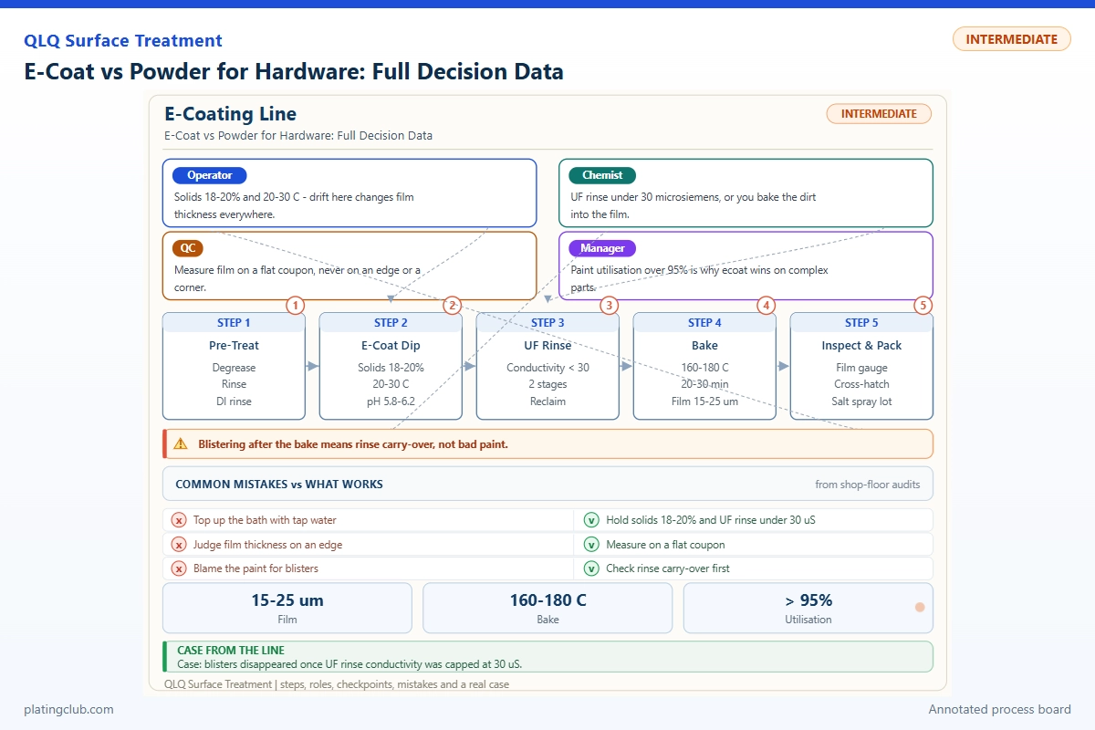
Painting engineering • Management-level decision guide
E-Coat vs Powder for Hardware: Full Decision Data
For a finishing plant, the winning coating is not the one with the largest salt-spray number. It is the system that protects the actual substrate, fits the assembly clearance, meets appearance requirements, and produces acceptable parts at sustainable cost. Zinc-alloy bag fittings, steel brackets, and moving zipper components should not share an unqualified coating specification.
Cathodic electrocoat deposits from an electrically controlled aqueous bath. Powder is deposited electrostatically and then fused and cured. Both require clean, compatible pretreatment and validated thermal exposure. This guide separates published laboratory evidence from plant qualification work, so management can approve a route without mistaking brochure performance for production capability.
1. Choose the system around the failure mechanism
| Decision factor | E-coat route | Powder route | Management gate |
|---|---|---|---|
| Recesses and moving interfaces | Thin film and immersion are useful; trapped air and poor contact still prevent coverage. | Recess deposition needs deliberate gun positioning; thick build can consume clearance. | Measure recess film and assemble coated parts. |
| Color portfolio | A dedicated bath favors stable, recurring volume. | Separate powder batches suit wider color portfolios; changeovers need cleaning discipline. | Calculate lost production and contamination rejects per change. |
| Outdoor appearance | Do not assume an epoxy primer is a weatherable finish. | Select an exterior-qualified chemistry, not merely a desired color. | Obtain the selected grade's weathering evidence. |
| Utilities and maintenance | Bath circulation, ultrafiltration, rinse recovery, water quality, and rectifier control need ownership. | Booth extraction, powder recovery, compressed air, and oven control need ownership. | Approve staffing and maintenance before equipment purchase. |
A combined e-coat primer and compatible powder topcoat is another route, not an automatic upgrade. Validate intercoat adhesion, total thickness, and the second bake on actual castings. A line manager should reject any proposal that cannot identify the limiting surface or the inspection method used to release it.
2. Experimental evidence: published panel controls
The following comparison uses manufacturer-reported test-panel data, not invented QLQ batches. Different substrates, pretreatments, and exposure durations prevent a direct durability ranking. “Not reported” must remain missing rather than being filled with a plausible hardness value.
| Published specimen system | Film thickness | Salt-spray result | Hardness / adhesion | Test condition |
|---|---|---|---|---|
| ARSONKOTE 212 2K white cathodic coating | 10–12 µm | 800 h; cross corrosion <2 mm; no blistering | Pencil hardness and cross-cut rating not reported | Bonder 26S W42 OC support; ASTM B117; application sheet lists 160–180°C / 15–20 min bake. |
| Interpon 600 polyester powder | 60–80 µm | 250 h; scribe creep <2 mm | Scratch hardness ≥H; adhesion 5B | Mechanical: 0.6 mm degreased steel. Chemical: Zn/Mn-phosphated steel or chromated aluminum. ISO 9227; ASTM D3363 / D3359; 200°C object temperature for 10 min. |
Sources: Arsonsisi test and application sheet, October 2013; AkzoNobel Interpon 600 laboratory data, August 2014. These historical references are evidence examples; obtain current grade-specific documentation before production.
Convert reference panels into a controlled plant trial
Split one identified casting or stamping lot between both routes. Use at least three independent processing batches per route and retain matched flat witness panels. Record substrate alloy, casting cavity, cleaning history, pretreatment, rack position, paint lot, thickness distribution, cure trace, and laboratory report number. Test edges, holes, and recesses as well as accessible faces.
Agree the corrosion endpoint before testing: exposure duration, scribe preparation, creep measurement, blister rating, and permitted failure. Use the same method on both routes. Add assembly fit, abrasion at moving contacts, and customer-relevant moisture exposure. The plant's results are currently pending; neither reference panel system constitutes a tested zinc-alloy bag-hardware specification.
3. Working Data & Formula Notes: complete commercial bath makeup
A coating bath is not made by mixing generic epoxy, pigment, and acid until the pH looks correct. The complete example below uses the matched commercial components specified for ARSONKOTE 212. It is a published building-block formulation, not disclosure of the supplier's proprietary resin synthesis.
| Component | Range | Typical | Function | Replenishment |
|---|---|---|---|---|
| Demineralized water, initial | Fixed charge | 400 L | Carrier | Water balance |
| Clear W 212 X 38 | Fixed charge | 193 kg | Binder package | Solids analysis |
| Pigment paste W 212 B 01 | Fixed charge | 87 kg | Pigment package | Composition analysis |
| Demineralized water, final | Fixed charge | 320 L | Dilution | Water balance |
The sheet gives no independent ingredient dosing tolerance: the Range column therefore preserves fixed charges. Add the specified packages sequentially under circulation, mix between additions, and condition the bath before trial coating. Confirm instructions with the supplier; do not substitute components or separately dose their internal additives.
For scale-up, use a supplier-approved multiplier on every charge. Do not call this a 1,000-liter batch by adding liters and kilograms. Component density and resulting bath volume matter. Replenishment is not perpetual repetition of startup proportions: deposition, drag-out, water loss, and recovery change the material balance.
For a simple solids correction, added concentrate mass = M × (starget − sbath) / (sfeed − starget). Here M is current bath mass and s values are mass fractions. This assumes homogeneous mixing and no simultaneous loss; it cannot establish pigment balance or justify an unapproved addition. Verify the calculated correction with the supplier and reanalyze after circulation.
Powder operators normally purchase formulated powder. Do not add resin, solvent, or hardener at the booth. Manage approved virgin/reclaim blending, sieving, contamination, and batch traceability instead.
4. Trend bands and danger thresholds
These are product-specific published windows. Leaving a window is an intervention threshold, not proof that failure starts at one universal number. Set earlier warning limits from stable production history. The e-coat rows apply only to the bath example above; they must not replace another grade's control plan.
| Parameter | Normal band | Danger / hold threshold | Action |
|---|---|---|---|
| E-coat solids | 10–12% | <10 or >12% | Confirm sampling and analysis before correction. |
| E-coat pH, 25°C | 5.8–6.8 | <5.8 or >6.8 | Investigate contamination and acid balance. |
| E-coat conductivity, 25°C | 900–1,300 µS/cm | Outside band | Check rinse carryover and electrode-cell operation. |
| E-coat bath temperature | 25–30°C | Outside band | Verify sensor and heat exchanger. |
| E-coat immersion | 120–150 s | Outside band | Check conveyor timing and full immersion. |
| Makeup-water conductivity, 25°C | ≤20 µS/cm | >20 µS/cm | Hold water addition and investigate treatment. |
| Interpon 600 reference film | 60–80 µm | <60 or >80 µm | Check gun setup, recess build, and assembly fit. |
Keep an hourly plot beside the batch record. A steady approach toward a boundary is actionable even while individual readings pass. Treat simultaneous pH and conductivity movement differently from an isolated temperature excursion. Check instrument calibration and sampling temperature before interpreting chemistry.
For cure, approve a complete time–part-temperature trace, not a single oven-air reading. The cited powder schedule requires ten minutes at 200°C object temperature. Different approved schedules or grades require separate recipes. Quarantine material after an unqualified trace; extending conveyor dwell without checking substrate and appearance can create another defect.
5. Two implementation scenarios to qualify
Scenario A: black zinc-alloy zipper components with tight clearance
This is an engineering scenario, not a claimed customer success. Start with the moving-contact drawing and identify surfaces that must remain uncoated or thin. Trial the selected e-coat on actual porous castings; check trapped air, contact marks, recess film, blistering, and post-bake assembly. A smooth witness panel cannot release a slider that binds. If the coating changes sliding force, revise masking or chemistry before scaling.
Scenario B: exposed colored steel bag brackets
This second scenario prioritizes appearance, outdoor exposure, and color changes. Trial a weatherable powder with suitable steel pretreatment. Compare flat and recessed film, corner appearance, mounting-hole clearance, and handling damage. Count booth-cleaning time and mixed-color rejects. If recess corrosion remains the limiting failure, investigate geometry and pretreatment before proposing an e-coat primer; qualify intercoat adhesion and double-bake exposure separately.
QLQ's local finishing notes support material-specific route selection and the importance of pretreatment, cure, adhesion, and corrosion checks. They do not provide matched experimental results for these scenarios. Assign a process engineer, quality owner, and completion date to each trial rather than turning assumptions into shipment claims.
6. Engineer Notes
- Photograph every approved rack configuration and mark electrical contact points. Strip buildup before it changes contact or masks a critical surface.
- Orient hollow hardware to vent air during immersion and drain after rinsing. Verify coverage by sectioning sacrificial parts, not visual inspection alone.
- Attach temperature probes to representative thin and heavy parts. Repeat profiling after load density, conveyor speed, or oven maintenance changes.
- Run one-variable trials for deposition or spray adjustment. Label samples immediately and retain the previous setup as the control.
- For cast zinc, investigate porosity and contamination before changing bake conditions to address pinholes. Validate any outgassing treatment on the alloy.
- Measure assembled fit after cure and cooling. Record functional force or clearance alongside thickness, rather than relying on a visual pass.
- Investigate abnormal UF recovery or powder-reclaim contamination before returning recovered material. Segregate suspect lots and document their disposition.
7. Shift Checks
| Shift stage | Check item | Frequency | Acceptance standard | Record |
|---|---|---|---|---|
| Before shift | Paint identity, recipe, calibration | Every startup or grade change | Approved grade and lot; instruments within calibration | Startup signoff and lot numbers |
| Before shift | Bath / water; booth and rack condition | Each startup | Applicable control bands; clean contacts; no foreign powder | Bath analysis or cleaning release |
| During shift | E-coat temperature, pH, conductivity | Hourly; after correction | Selected grade's approved windows | Trend chart and addition log |
| During shift | Film, recess coverage, appearance, fit | First rack; hourly; after adjustment | Approved drawing and qualification limits | Position-based measurements |
| During shift | Cure trace and conveyor setting | Startup; after load or setting change | Qualified time–part-temperature profile | Profile identifier and recipe revision |
| After shift | Consumption, rejects, recovery, hold lots | Each shift close | Material balance reconciled; unresolved lots segregated | Handover and quality disposition |
Quality owns release; operators own recording; maintenance owns equipment restoration. Establish who can stop the line and who approves restart. Never average a failed critical-surface measurement into a passing batch mean.
8. Approve economics using accepted output
Cost per accepted part = total period coating cost / accepted parts shipped. Include paint, pretreatment, water, electricity, oven energy, labor, rack stripping, filtration, waste treatment, maintenance, changeovers, rework, and allocated capital. Separate startup losses from steady-state performance.
Calculate deposited film demand from coated area × dry thickness × cured-film density. Use actual material density and measured geometry. Purchase demand additionally includes net losses and recovery efficiency; a recovery percentage alone cannot establish cost. Record these inputs during the trial instead of borrowing another factory's utilization claim.
Management should approve a route only after quality, capacity, and financial gates all pass. A cheaper kilogram of coating can produce a more expensive accepted fitting. Retain a fallback recipe and inventory plan while production capability is established.
9. Technician-to-AI FAQ
These are practical technician-to-AI prompts, not quotations attributed to named customers.
“AI, our e-coat panels pass salt spray, but the zipper parts fail inside the recess. What should I check first?”
Check actual recess thickness, trapped air, rack contact, pretreatment access, and drainage. Compare failed and sound parts from the same rack. Preserve bath readings and cure traces before adjusting voltage. Panel success does not establish part coverage.
“AI, can I replace e-coat with powder and keep the same clearance drawing?”
Not without a fit trial. Measure both mating surfaces after cure, including recess buildup and masking boundaries. Update the coating allowance only after assembly and functional tests. A powder's panel thickness is not permission to close a moving gap.
“AI, which salt-spray number should management use to choose the cheaper line?”
Use matched substrate and pretreatment trials with one agreed endpoint. Then compare accepted-part cost at the required capacity. The published numbers here use different conditions and cannot establish a universal winner or predict service life.
What Would You Like to Solve?
Send your alloy, part drawing, critical clearances, finish target, test protocol, current reject pattern, and daily accepted output to [email protected]. Include current paint documentation and oven traces so the review can identify missing qualification evidence. For coordinated equipment, chemistry, and process planning, see turnkey surface-treatment line support.
Local knowledge basis: QLQ Obsidian Vault, IMA company knowledge split, note 032, Electrophoretic Coating Process; Slider Electroplating and Painting, slider-process folder. General internal ranges are not substituted for the grade-specific formulation above. Customer cases and matched zinc-alloy test reports: not available in the reviewed sources; confirmation required.