
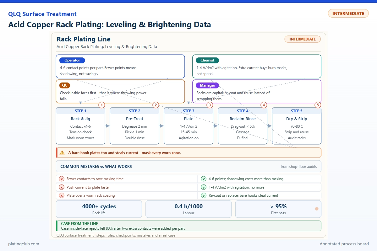
RACK PLATING / JUNIOR TECHNICIAN / WORKING DATA
Acid Copper Rack Plating: Leveling & Brightening Data
A shiny copper surface is not proof of a leveled surface. For technicians with three or more years of shop experience, the practical task is to separate additive balance from current distribution, verify the undercoat, and make one controlled correction at a time. This guide turns those decisions into measurable checks rather than repeated brightener additions.
1. Confirm the substrate before diagnosing brightness
For zinc-alloy bag hardware, acid copper is a build-up layer over an approved, continuous strike or barrier coating, not a direct treatment of bare zinc. Exposed zinc can dissolve and contaminate the bath; a bright-looking deposit can still blister later. Confirm the authorized alkaline copper route, coverage at holes and edges, and transfer sequence before loading the acid tank.
The QLQ knowledge-base note 049 — Machine-setting Technician Experience explicitly warns against ordinary acid copper directly on zinc. Its associated rack-line compilation confirms that acid-copper additives are separate process consumables but does not supply a complete concentration sheet or comparative coupon results. Consequently, the numerical references below are identified as external data, not QLQ production measurements.
Keep any cyanide-bearing upstream operation physically and procedurally segregated from acids. Use approved rinsing, extraction, personal protection, and the chemical supplier's safety instructions. Junior technicians must not improvise bath make-up or contamination treatment.
2. Brightening, leveling, and thickness are different results
Brightening changes how the deposit reflects light through its surface structure. Leveling reduces a defined scratch or groove because deposition differs between peaks and valleys. Throwing power describes thickness distribution across geometrically different regions. A bright front face with thin recessed areas may therefore fail the drawing even when its appearance passes.
Use identical witness coupons with a reproducible groove, fixed rack position, and documented preparation. Measure groove depth before and after plating at registered locations. Calculate leveling as 100 × (initial depth − final depth) / initial depth. A groove reduced from 10 to 4 micrometers gives 60% leveling; this is an arithmetic example, not a reported experiment. Record local copper thickness alongside the result so that a thicker deposit is not mistaken for a better additive balance.
Photograph dry coupons under fixed lighting. If using a gloss meter, record its geometry and instrument identification. Do not compare informal brightness scores collected under different lamps.
3. Complete reference formulation and replenishment discipline
The following single-package example follows the published FI-970 acid-copper entry in the Fengfan parameter center. It is an external reference, not a QLQ formulation or a recommendation to mix brands. Midpoints marked below are editorial working targets. Confirm the supplier's copper-sulfate hydration basis and current technical sheet before weighing material.
| Component | Range | Typical | Function | Replenishment |
|---|---|---|---|---|
| Copper sulfate | 200–220 g/L | 210 g/L midpoint | Copper source | Analyze; account for soluble-anode supply before adding salt. |
| Sulfuric acid, pure-acid basis | 55–70 g/L | 62.5 g/L midpoint | Conductivity and acidity | Titrate; correct by authorized diluted addition. |
| Chloride ion | 100 mg/L target; no band published | 100 mg/L | Additive-system interaction | Assay before any chloride correction. |
| FI-97 MU | 4–8 mL/L | 6 mL/L midpoint | Package make-up component | Follow supplier analysis and drag-out guidance. |
| FI-97 A | 0.4–0.6 mL/L | 0.5 mL/L midpoint | Package additive A | Supplier-specific ampere-hour dosing and panel confirmation. |
| FI-97 B | 0.4–0.6 mL/L | 0.5 mL/L midpoint | Package additive B | Supplier-specific dosing; do not substitute A. |
| Approved deionized water | Quantity sufficient | Final operating volume | Solvent | Restore level before sampling; distinguish evaporation from drag-out. |
The molecular roles inside proprietary MU, A, and B concentrates are not disclosed here; assigning them to specific suppressor, accelerator, or leveler chemicals would be speculation. Obtain the supplier's maintenance instructions rather than inventing a universal mL/kAh rate.
For a measured deficiency, calculate the required active material from concentration difference multiplied by actual bath volume, then correct for reagent assay. For example, increasing a 1,000-liter bath by 5 g/L requires 5 kg of the specified active material before purity correction. Have the bath-control technician authorize the addition and the preparation method; use controlled acid-to-water dilution, never water into concentrated acid.
4. Published experimental comparison: read the conditions first
US8679317B2, Table 2 reports the following measured coupon results. These are patterned electronic substrates, not bag-hardware trials. They illustrate additive-dependent thickness distribution; they do not certify decorative performance.
| Trial | Test condition | Pad center thickness | Pad edge thickness | Via recess | Void |
|---|---|---|---|---|---|
| Example 1 | 2 A/dm², 45 min; 60 µm diameter × 60 µm deep vias; 35 µm resist; 200 µm pad width | 20 µm | 20 µm | 15 µm | None |
| Example 2 | Same geometry, current density, and time | 19 µm | 20 µm | 5 µm | None |
| Example 4 | Same geometry, current density, and time | 18 µm | 25 µm | Not reported | Present, type b |
The patent uses 200 g/L copper sulfate pentahydrate, 50 g/L acid, 50 mg/L chloride, and 1 mg/L SPS. Carrier and leveler chemistry vary: Example 1 uses PO-EO with leveler A; Example 2 uses PPG with A plus C; Example 4 uses PEG with C. Multiple variables changed, so this is not a leveler-only dose study.
For a shop experiment, compare an unchanged bath sample against one authorized adjustment using the same coupon, agitation, and current program. Run three coupons per condition; report individual results and their spread. Include adhesion and minimum thickness. Salt-spray performance belongs to the complete finishing stack, not a copper brightness photograph. No bag-hardware salt-spray or hardness result is available here.
5. Normal trend bands versus intervention thresholds
The bands below are proposed commissioning controls, not universal defect boundaries. Chemical limits follow the reference package; temperature and current targets are conservative starting settings for trials. The engineer must approve them against the actual additive sheet, rack geometry, and coupon results before production. An intervention threshold means hold and investigate, not proof that a particular defect must occur.
| Parameter | Normal working band | Danger / hold threshold | First action |
|---|---|---|---|
| Copper sulfate | 205–215 g/L internal target | Below 200 or above 220 g/L | Repeat analysis; check volume and anode balance. |
| Pure sulfuric acid | 60–65 g/L internal target | Below 55 or above 70 g/L | Repeat titration; obtain correction approval. |
| Chloride | 95–105 mg/L provisional band | Below 90 or above 110 mg/L provisional alarm | Confirm analytical uncertainty and supplier limits. |
| Temperature | 24–28 °C trial target | Outside 20–35 °C reference envelope | Check cooling and temperature sensor. |
| Average cathode current density | 2–3 A/dm² trial target | Outside the approved rack recipe; never assume edges equal the average | Recalculate wetted area and inspect contacts. |
| Witness-coupon minimum thickness | Within the job's approved thickness tolerance | Any reading below drawing minimum | Hold the load; cross-check measurement calibration. |
| Rectifier current stability | Within ±5% of recipe setpoint, proposed control | Deviation exceeding ±10%, proposed alarm | Check connections and rectifier under load. |
Do not import a pH 4.2–4.8 window from another plating chemistry. This strongly acidic sulfate bath is controlled by free-acid analysis, not routine pH adjustment. Never add alkali to chase a pH number. Distinguish a gradual concentration trend caused by drag-out from a sudden step caused by an addition, sampling error, or water-level correction.
6. Two diagnostic situations for the rack operator
Situation A: bright faces, visible polishing lines
This is a troubleshooting scenario, not a claimed customer case. Retain an unplated part from the same polishing lot. Compare groove depth and plated thickness on its matched coupon. If adequate copper thickness leaves the groove largely unchanged, request a controlled additive-balance trial. If the original scratches are unusually deep, return the issue to polishing rather than consuming more brightener. Save photographs and measurements with the lot number.
Situation B: rough tips, dull recesses after a loading change
Restore the last approved rack layout for a comparison load. Verify total wetted area, tip spacing, orientation, and electrical contact. A changed part count can change current density even when the rectifier display is unchanged. Have the engineer assess shields or auxiliary anodes if distribution remains poor. Do not treat every dull recess as additive starvation; first establish that current reaches it consistently.
7. Engineer Notes: seven actions worth recording
- Identify the exact additive package and revision of its technical sheet; block additions from unlabeled or incompatible containers.
- Sample after restoring bath level and completing the approved mixing interval. Label the sample with time, temperature, and recent additions.
- Inspect rack contact points before loading. Clean them only by the approved maintenance procedure, then check for excessive voltage drop under load.
- Use the supplier's standardized Hull-cell procedure. Record current, duration, agitation, and panel preparation before comparing panels.
- Make one laboratory correction at a time. Reserve an unchanged control sample, and do not scale a favorable panel result directly to the tank without authorization.
- Inspect anode bags and filtration when roughness appears. Schedule repairs safely; never dismantle energized equipment or prescribe carbon treatment without an additive-restoration plan.
- Retain matched coupons and addition records until the downstream finish passes inspection. Track the cumulative ampere-hours associated with each approved dose.
8. Shift Checks
| Shift stage | Check item | Frequency | Acceptance criterion | Record |
|---|---|---|---|---|
| Before shift | Bath identity, level, main chemistry | Every start; chemistry at approved analysis interval | Correct package; marked volume; signed analysis within limits | Bath ID, analysis, operator |
| Before shift | Strike coverage, rack contacts, extraction | First rack and after maintenance | No exposed substrate; approved contacts and safety systems functioning | Rack ID, checklist, exceptions |
| During shift | Current, time, temperature, rack loading | Every load; temperature hourly | Approved recipe and normal trend bands | Load ID, area, amperes, minutes, temperature |
| During shift | Coupon appearance and minimum thickness | First load, every four hours, after adjustment | Approved master appearance; drawing minimum met | Coupon ID, measurement sites, readings |
| During shift | Additive dosing and bath response | Every addition | Authorized dose; mixing completed; comparison panel accepted | Chemical lot, volume, kAh, approval |
| After shift | Reconciliation and next-shift handover | Every finish | No unexplained additions; held loads identified; alarms communicated | Consumption, holds, trend chart, signatures |
9. Technician-to-AI FAQ
These are suggested first-person prompts, not quotations attributed to real customers.
“My copper is shiny, but the polishing scratches are still there. Should I add more brightener?”
Not before checking thickness and original scratch depth. Share matched coupon measurements, additive identity, analysis, and the last additions. Ask the bath-control technician for a control-versus-adjusted sample comparison. Brightness alone does not tell you whether the leveling component is correct.
“Only the tips burn after I changed the number of parts on the rack. What should I check first?”
Recalculate the wetted area and compare rack spacing with the approved layout. Inspect contacts and verify actual current. Restore the prior layout for a controlled comparison. Record whether the defect follows rack position or the individual part before asking for a chemical correction.
“The bath pH reading looks wrong. Can I add caustic to bring it back?”
No. Identify the bath, confirm its sulfuric-acid titration, and check sampling conditions. Do not neutralize an acid-copper bath based on a borrowed pH range. Escalate an unexpected reading and follow the approved analytical method rather than introducing an uncontrolled contaminant.
10. What Would You Like to Solve?
For a specific diagnosis, send the substrate and strike route, additive package, recent bath analyses, rack area, current/time settings, and matched photographs. Include the location and thickness of the defect rather than only describing it as “not bright.” Email [email protected] or review integrated surface-treatment line, chemistry, and process support. Follow Huige for practical process discussions.
Local source files: QLQ-Obsidian-Vault/02-Product-Knowledge/IMA-Company-Knowledge/049 — Machine-setting Technician Experience; QLQ-Obsidian-Vault/02-Product-Knowledge/07-Surface-Treatment/Plating, Barrel, Rack and Electrocoating Lines and Formulations — W-drive Compilation. English source labels translate the local note titles. External formulation and experimental sources are linked where used; proposed controls and illustrative situations require local engineering validation.