
A zip slider plates beautifully on every flat face — and the inside of its cavity stays bare. A bracket comes out of the zinc bath with crisp, bright edges and grey, powdery corners. Every plating shop knows this part, and it is one of the most common samples we are asked to rescue: the geometry plated unevenly, and no amount of extra time in the tank fixes it.
The cause is a property of every electrolyte called throwing power — how uniformly the bath deposits metal across a part with recesses, cavities, and high points. This guide explains why current refuses to reach inside a recess, and the four-step fix sequence our engineers use on real lines.
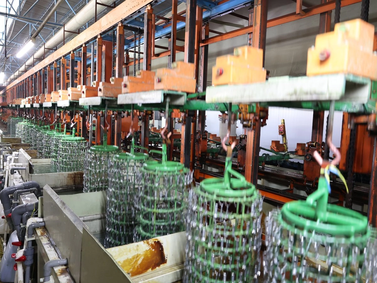
Why Current Avoids Recesses
Current takes the path of least resistance. On a shaped part, the edges and points present the shortest ionic path and the highest local current density; deep cavities and inner diameters present a long, restricted path and receive almost nothing. The result: burnt, over-plated high points next to thin or bare low-current-density areas.
Two terms matter and they are not the same thing:
- Throwing power (throwing index): how uniformly the bath spreads thickness across the whole part.
- Covering power: whether the recess plates at all.
A bath can have good covering power (something deposits everywhere) but poor throwing power (the recess is 1 µm while the edge is 20 µm). Cyanide zinc and alkaline zinc are famous for good throwing power; decorative bright acid baths are weaker — which is exactly why complex die-cast parts often plate unevenly in bright nickel.
The Four-Step Fix (in order)
Step 1 — Check the actual current density, not the rectifier dial.
Low-current-density areas are the first to starve when total current is set too low. Compute A/dm² from the real wetted area of the part — not tank wall area, and not "we usually run 300 A". For complex parts with deep recesses, running at the top of the bath's normal CD window often lifts the recesses into the plating range without burning the edges.
Step 2 — Add a helper where current will not go: auxiliary and conforming anodes.
For deep cavities, cups, and inner diameters, a conforming (pic-shaped) anode placed inside the recess shortens the current path — this is the standard fix for deep-drawn shells and slider bodies with closed backs. The flip side: robbers/shields (non-conductive or metal shields) placed near edges cut the excess CD at high points. Auxiliary anodes and shields are the two ends of the same balancing act: move metal thickness from where there is too much to where there is too little.
Step 3 — Use a strike to force initial coverage.
A strike plating step — a short burst of high current density as parts enter the bath — forces initial deposits into recesses before the current is returned to normal. Once a thin layer covers the recess, the main plating proceeds evenly. Strikes are standard practice on bright nickel over zinc die-cast and on acid zinc over difficult geometries.
Step 4 — Rule out contact problems before blaming chemistry.
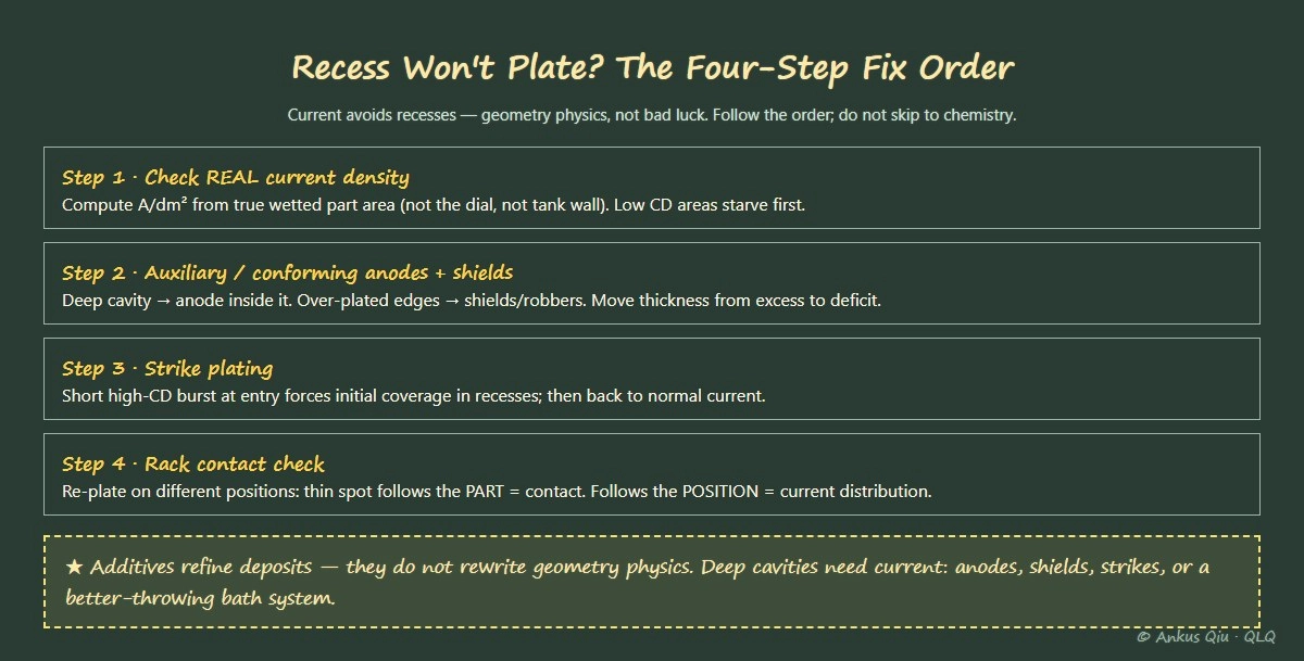
A worn rack tip or a loose contact adds resistance, and that individual part plates thin — especially at its own low-current areas. The discriminator is simple: re-plate the suspect parts on different rack positions. If the thin spots follow the part, it is rack contact (or the part itself). If they follow the position on the rack, it is current distribution.
Bath Choice Matters More Than Any Additive
If a complex part consistently shows bare recesses, the honest engineering answer may be that the bath chemistry is wrong for the geometry:
| Need | Better choice | Why |
|---|---|---|
| Deep recesses must be covered | Alkaline zinc / cyanide-type systems | Highest throwing power |
| Balanced coverage + brightness on open parts | Acid chloride zinc | Bright, fast, weaker in deep recesses |
| Barrel-plated small parts | Barrel baths chosen for throwing power | Parts tumble; coverage depends on bath |
No proprietary additive turns a poor-throwing bath into a good one. Additives refine the deposit; they do not rewrite geometry physics.
Real Line Example
A zipper slider body (zinc alloy, closed-back cavity) came off a bright nickel line with a grey, un-plated cavity floor. The rectifier was running well below the calculated A/dm² because operators feared burning the visible faces. We recomputed CD from true part area (it was 30% under the window), raised total current into range, and added a 30-second nickel strike at start-up. Cavity floors covered fully; edges stayed within brightness tolerance. No bath change, no additive shopping.
FAQ
Q: Will longer plating time eventually fill the recess?
A: No. If current density at the recess is near zero, extra time deposits almost nothing there — it just over-plates the edges. Fix current distribution instead.
Q: Our supplier says their additive fixes coverage. True?
A: Additives can modestly improve throwing power and grain refinement, but a recess that receives almost no current will stay bare. Geometry needs current — anodes, shields, strikes, or a better-throwing bath system.
Q: Barrel plating solves this, right?
A: For small parts, barrels help because parts tumble and every face sees the anode periodically. But deep cavities still plate last; critical recess specifications still need trials, not assumptions.
Q: How do we specify this to a plating equipment supplier?
A: Send part drawings with the recess dimensions marked, the base alloy, and your thickness specification per surface. A serious supplier answers with an anode layout, expected thickness distribution, and — for hard cases — a trial panel plan.
About the author: Ankus Qiu — senior process engineer at QLQ (Guangzhou QLQ Enterprise Co., Ltd.), 25 years designing barrel- and rack-plating lines for zipper sliders and hardware. QLQ supplies complete plating lines with in-house chemical systems and on-site process support; ISO 9001 certified, exporting to 70+ countries. Verify all parameters against your supplier's TDS for your specific system.