

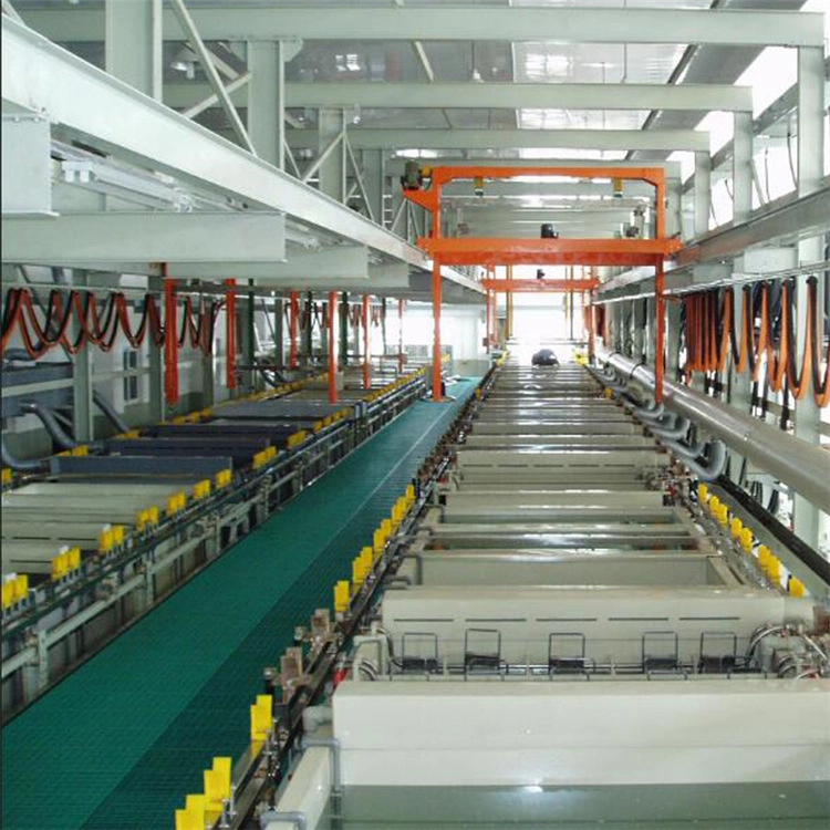
Recesses measured 3 µm while flat faces reached 20 µm, a coverage gap the customer rejected for interior corrosion risk. Voltage ramp and part position, not paint chemistry, closed the gap.
This intermediate guide sets the ramp window, part orientation and anode spacing checks that build film inside the hard spots.
Common Mistakes and How to Avoid Them
| Mistake | Why It Happens | Practical Fix |
|---|---|---|
| 1. Voltage slammed to full | Rupture on edges, starved recesses | Ramp over 30-60 s |
| 2. Ramp too slow | Time wasted, thin build | Match ramp to the part |
| 3. Recess facing the rack bar | Bar shadow | Orient recess outward |
| 4. Position fixed for one part | New geometry fails | Set position per part card |
| 5. No section check | Thin recess hidden | Section a sample per batch |
| 6. Conductivity drift | Throw power changes | Check conductivity weekly |
| 7. Anode distance uneven | One side thick | Set spacing per rack |
| 8. Pendant shadow | Stripes on the surface | Check adjacent parts |
| 9. Only flat parts measured | Recess ignored | Measure the worst location |
Best Practices
- Ramp voltage over 30-60 seconds to target
- Orient recesses away from rack bars
- Set part position per part card
- Section recess samples each batch
- Check bath conductivity weekly
- Log ramp, position and recess thickness
Implementation Roadmap
| Step | Frequency |
|---|---|
| Set the ramp | Per part change |
| Orient parts | Per load |
| Section sample | Per batch |
| Conductivity check | Weekly |
| Review coverage log | Monthly |
Recess coverage tuning flow
- Ramp - 30-60 s to target. (Full voltage ruptures edges.)
- Position - Recess outward. (Bar shadow starves the spot.)
- Verify - Section the recess. (Surface looks fine, inside thin.)
- Adjust - One variable per trial. (Multi-change unprovable.)
Voltage ramp controls throw into recesses. | Position decides which surface faces the current.
E-coat recess film data
Reference values for cathodic e-coat recess coverage tuning.
| Parameter | Reference | Why It Matters |
|---|---|---|
| Bath solids | 15-20% | Feed per consumption |
| Bath pH | 5.8-6.4 | Set with acid or base dosing |
| Conductivity | 25-60 µS/cm | Holds throw power |
| Voltage | 120-250 V | Ramp to target |
| Ramp time | 30-60 s | Protects edges, feeds recesses |
| Dip time | 60-180 s | Longer builds recess film |
| Recess thickness | 8-15 µm typical | Section to verify |
| Anode spacing | Per rack | Even distance, even build |
Recess coverage tuning card
| Variable | Setting | Effect |
|---|---|---|
| Ramp time | 30-60 s | Edges safe, recess fed |
| Recess orientation | Away from the bar | Less shadow |
| Conductivity | Per target | Throw power |
| Section check | Deepest point | Real coverage |
Case 1 - recess film lifted from 3 to 12 µm by ramp and position tuning
Scenario. A line producing cast housings measured 3 µm in the deepest recess against 20 µm on flats; the customer rejected the lot for interior corrosion risk.
Action. Voltage was ramped over 45 seconds, housings were re-oriented with recesses facing the anode, and a section sample was checked every batch.
Result. Recess film reached 12 µm against the 8 µm minimum; the re-run passed, and the orientation rule went on the racking card.
Case 2 - an automotive mirror bracket fixed by anode spacing
Scenario. A mirror bracket with a deep cup showed 5 µm inside the cup but 22 µm on the face, while the bath and ramp matched the product sheet.
Action. The rack was repositioned away from the side wall, anode spacing was evened out, and the cup orientation was rotated toward the anode.
Result. Cup film rose to 10 µm with faces at 18 µm; the spacing layout was drawn on the racking board.
Frequently Asked Questions
Why is recess film thinner?
Current follows the shortest path; recesses see less field and less solution exchange.
How does the ramp help?
A slow ramp lets the field build before film resistance rises, pushing coverage deeper.
What ramp time works?
30-60 seconds to target is the common window; tune by part geometry and film target.
Why does orientation matter?
The side facing the anode gets the strongest field; turn the recess toward it.
What about rack bar shadow?
The bar between the anode and the part screens current; keep parts clear of bars.
How do I verify recess coverage?
Section the part at the deepest point and measure the film; surface checks hide it.
Does conductivity matter?
Yes - it drives throw power; drift changes how deep the film builds.
What if one side is thicker?
Check anode distance and rack position; uneven spacing gives an uneven field.
Can longer dip time help?
Within 60-180 s, longer time builds more recess film but watch edge thickness.
What is the fastest fix order?
Ramp, then orientation, then spacing; change one variable per trial.
What Would You Like to Solve?
Describe your part geometry, ramp settings, rack layout and where the film measures thin. We can help set the ramp window and position rules for your line.