
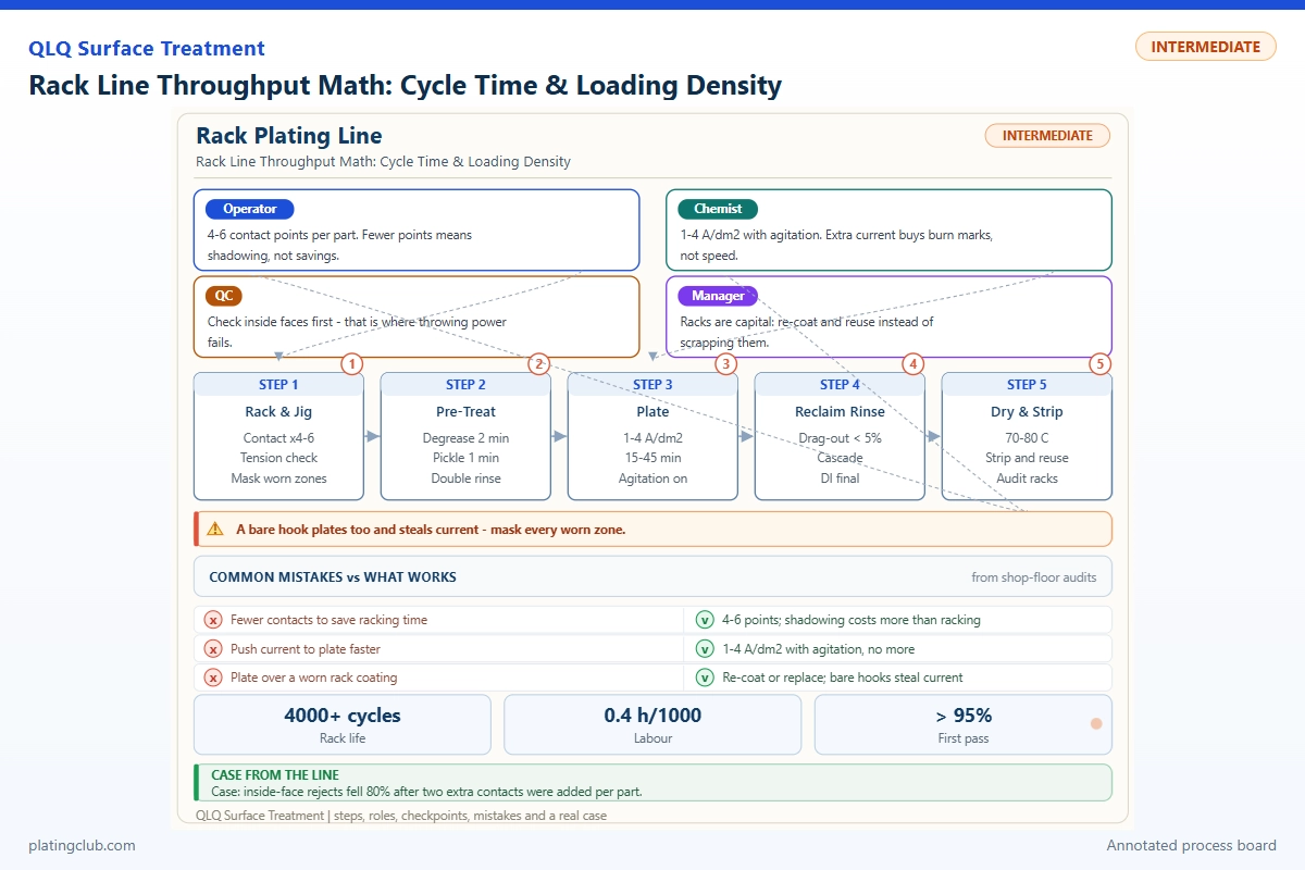
RACK PLATING / MANAGEMENT ENGINEERING
Rack Line Throughput Math: Cycle Time & Loading Density
A rack line earns capacity through accepted parts, not crowded hooks. Management must connect dispatch interval, plated surface area, electrical capacity, coating distribution and first-pass yield. Increasing rack count can shorten the order queue while quietly creating a larger rework queue.
This guide separates published coupon results from hypothetical capacity calculations. The nickel example is a planning reference, not a universal recipe for zinc-alloy bag hardware. Substrate preparation, undercoats, finish specification and chemical-supplier approval remain separate release gates.
1. Measure three clocks before changing the schedule
Residence time is how long a rack remains in one operation. Dispatch interval is the time between successive racks entering the line. Total lead time includes every treatment, transfer, queue, inspection and unloading operation. A twenty-minute nickel dwell does not necessarily mean only three racks per hour: several independently supplied rack positions may operate concurrently.
For each stage, determine occupied time, including any transfer or drainage that prevents reuse of its position. Divide that time by the number of genuinely independent positions. The largest result sets a theoretical lower bound on dispatch interval. A shared hoist, shared rectifier or incompatible route can make the actual interval longer.
Minimum interval bound: T ≥ max(ti / mi, H, L).
Here T is minutes per dispatched rack; ti is stage occupancy; mi is simultaneous usable positions; H is shared-hoist service minutes per rack; L is loading-station service minutes per rack after accounting for parallel operators.
Accepted output: Q = (60 / T) × N × A × Y.
N is pieces per rack, A is operating availability and Y is first-pass yield. Use availability only for losses not already embedded in the measured dispatch interval.
These are screening equations, not a collision-free hoist schedule. Check interlocks, mandatory transfer windows and route conflicts through a timed schedule. For mixed finishes, calculate by route family; averaging incompatible dwell requirements hides the real bottleneck.
2. Loading density is an area-and-current decision
Measure wetted plated area, including backs, edges and internal surfaces that actually receive current. Exclude intentionally masked areas, but include exposed rack metal when assessing total rectifier demand. Record piece count separately from plated area: two similarly sized buckles can have different electrical loads.
For an illustrative rack carrying 120 parts at 0.50 dm2 each, part area is 60 dm2. A nominal 4.0 A/dm2 requires 240 A for the parts, plus any rack losses. Increasing to 150 parts raises area to 75 dm2 and demand to 300 A. If current remains 240 A, average part current density falls to 3.2 A/dm2.
Nickel thickness estimate: d = 0.205 × η × J × t.
d is micrometres, η is cathodic efficiency as a fraction, J is A/dm2 and t is energized minutes. The coefficient follows Faraday's law using nickel molar mass 58.69 g/mol, two electrons per atom, density 8.90 g/cm3 and Faraday constant 96,485 C/mol.
At an assumed efficiency of 0.95, 4.0 A/dm2 for twenty minutes predicts 15.6 µm average thickness. At 3.2 A/dm2, it predicts 12.5 µm. Neither value certifies the thinnest recess. Establish the ratio between minimum local thickness and average thickness from production measurements, then use that ratio when setting dwell.
Freeze orientation, spacing and anode distance in the rack drawing. A higher hook count is useful only when solution exchange, gas escape, contact reliability and minimum local thickness remain acceptable.
3. Working Data & Formula Notes: additive-free Watts nickel
The published laboratory bath used nickel sulfate heptahydrate at 300 g/L, nickel chloride hexahydrate at 45 g/L and boric acid at 45 g/L, with pH 4.5 and temperature 60 °C. The narrow ranges below are proposed commissioning control bands around that reference, not published commercial formulation limits.
| Component | Range | Typical | Function | Replenishment |
|---|---|---|---|---|
| NiSO4·7H2O | 285–315 g/L | 300 g/L | Nickel-ion source | Maintain soluble anodes; correct analyzed deficit with dissolved, filtered salt. |
| NiCl2·6H2O | 40–50 g/L | 45 g/L | Anode dissolution and conductivity | Analyze chloride; replace drag-out losses by calculated additions. |
| H3BO3 | 40–48 g/L | 45 g/L | Cathode-interface buffering | Analyze; dissolve corrections before addition. |
| Deionized water | Final working volume | Balance to 1 L | Solvent | Restore evaporation losses to the calibrated level before analysis. |
| Brightener / wetter | 0 for this reference | None | Excluded from the studied bath | Do not introduce commercial additives without a separately qualified formulation. |
Hydration state matters: heptahydrate and hexahydrate sulfate masses are not interchangeable. For concentration correction, addition mass in kilograms equals concentration deficit in g/L multiplied by working litres, divided by 1,000; correct for assay. Confirm dissolution and reanalyze before release.
This base bath is not a bright decorative finishing package. Zinc-alloy components need a substrate-compatible preparation and undercoat route; do not place bare zinc die castings directly into this example. Nickel salts require controlled handling, extraction and appropriate waste treatment. Follow current supplier safety instructions and local requirements.
Reference: Boukh ouiete and colleagues, 2021 nickel electrodeposition study, Table 1.
4. Experimental evidence: faster deposition does not preserve every property
| Coupon condition | Current density | Thickness | Vickers hardness | Test condition |
|---|---|---|---|---|
| Low-current specimen | 1 A/dm2 | About 50 µm | 355 HV | Additive-free Watts bath; nickel substrate; 60 °C; pH 4.5; 200 rpm stirring; 200 g indentation load, 20 s hold. |
| Medium-current specimen | 5 A/dm2 | About 50 µm | 245 HV | Same bath, substrate, temperature, pH, stirring and hardness method. |
| High-current specimen | 10 A/dm2 | About 50 µm | 250 HV | Same bath, substrate, temperature, pH, stirring and hardness method. |
Source: published methods and Table 4. These results do not establish rack-line acceptance limits or zinc-alloy corrosion performance.
For a plant loading trial, compare baseline, denser loading at unchanged current, and denser loading at area-corrected current. Run at least three racks per condition as an initial engineering screen. Map identical edge, centre and recess locations; record minimum thickness, appearance, adhesion and accepted count. Increase sampling when variability demands it. Salt-spray duration, rating method and complete coating stack must come from the customer specification, not from a throughput formula.
5. Trend bands and stop-change thresholds
These are example internal controls for a commissioned reference process, not universal defect thresholds. Validate them locally. “Danger” means stop the capacity experiment, investigate and segregate suspect racks; it does not mean every part automatically fails.
| Parameter | Normal fluctuation band | Danger / hold threshold | Required response |
|---|---|---|---|
| Bath pH | 4.3–4.7 | Below 4.0 or above 5.0 | Verify calibrated sample measurement; restore the approved setpoint. |
| Temperature | 58–62 °C | Below 55 or above 65 °C | Check independent probe, heater and circulation. |
| Average part current density | 3.8–4.2 A/dm2 | Below 3.6 or above 4.4 | Reconcile actual area and measured current before proceeding. |
| Energized dwell | 19.5–20.5 minutes | Below 19 or above 21 | Inspect timer events and power interruptions. |
| Contact voltage drop | Within ±20% of clean-rack baseline | Above 150% of baseline at equal current | Remove rack for contact cleaning and inspection. |
| Circulation flow | 90–110% of qualified flow | Below 80% | Check pump, filter restriction and nozzle distribution. |
| Minimum local thickness | At least 110% of specified minimum | Below specified minimum | Hold batch and diagnose distribution; the margin is a proposed internal target. |
Trend readings against rack identity and area, not just clock time. Contact deterioration often appears as increasing voltage at comparable current before visible defects become obvious. Assign each alarm an owner and a documented restart condition.
6. Two management scenarios: find the constraint that actually moves
Scenario A: additional hooks, unchanged electrical supply. This hypothetical line has four nickel positions occupied for twenty minutes each, giving a five-minute interval bound. At 120 parts, 90% availability and 98% first-pass yield, accepted output is 1,270 parts/hour. A proposed 150-part rack at the same 240 A needs twenty-five energized minutes to preserve the calculated average thickness.
Nickel capacity then limits dispatch to 6.25 minutes. At unchanged availability and yield, output remains 1,270 parts/hour: extra pieces have bought extra dwell, not extra capacity. If yield falls, accepted output declines. Management should investigate contact and current-distribution capability before approving the denser layout.
Scenario B: sufficient current, insufficient loading labour. Suppose a qualified 150-part layout can receive 300 A and retain twenty-minute dwell. Its nickel interval bound remains five minutes, but loading requires six minutes per rack. Actual output becomes 1,323 parts/hour at the same availability and yield, not the theoretical 1,588.
A second loading station may remove that constraint, but only if staffing, rack return and unloading can support it. Before buying another plating tank, time each handling operation and simulate hoist conflicts. Both scenarios are calculations, not customer case histories or promised machine capacities.
7. Engineer Notes
- Build an area register. Attach measured area, approved orientation and allowed count to every rack recipe; require engineering sign-off after product geometry changes.
- Measure contacts under load. Compare voltage drop at equal current using an approved safe test procedure; isolate equipment before repairing hooks or bus connections.
- Separate dwell from power-on time. Export rectifier events and hoist timestamps so immersion without current cannot masquerade as productive deposition.
- Map the weakest locations. Mark repeatable measurement points on representative parts and reject density changes that reduce minimum coating below specification.
- Change one constraint at a time. Test spacing before simultaneously changing current, agitation and additives; retain the baseline rack for comparison.
- Protect transfer windows. Maintain qualified drainage and rinse times; do not recover schedule losses by bypassing cleaning, rinsing or extraction interlocks.
- Review accepted-output economics. Compare labour, electricity, chemical drag-out and rework cost per accepted thousand pieces, not per dispatched rack.
8. Shift Checks
| Shift stage | Check item | Frequency | Acceptance criterion | Record |
|---|---|---|---|---|
| Before shift | Rack contacts, insulation and recipe | Every rack before loading | Approved drawing; no damaged insulation; clean, secure contacts | Rack ID and inspection signature |
| Before shift | pH, temperature, level and flow | Before first production rack | Qualified bands; extraction and safety interlocks functional | Bath log and instrument ID |
| During shift | Area, current and energized dwell | Every rack; automated where possible | Matched recipe and approved trend bands | Rack trace with power events |
| During shift | pH, temperature and circulation | Hourly; continuous temperature/flow alarms | No unresolved excursion | Trend, correction and responsible person |
| During shift | Minimum thickness and appearance | First rack, after change, then approved sampling plan | Drawing minimum and finish specification met | Location map and measurement results |
| After shift | Output, rejects and stoppages | Each shift | Counts reconciled; suspect material identified | Accepted-output report and loss codes |
| After shift | Bath analysis and additions | Daily or validated usage-based interval | Analysis approved before corrective dosing | Assay, calculation and next-shift handover |
9. Technician-to-AI FAQ
These are practical example prompts, not quotations from customer correspondence.
“AI, can I add 25% more parts to each rack without increasing cycle time?”
Only after confirming current capacity and coating distribution. Calculate the new area, increase current proportionally if the qualified process permits it, then verify recess thickness and contacts. At fixed current, adding 25% area reduces average current density by 20%, so unchanged dwell deposits less average thickness.
“AI, why did our racks per hour improve but our good parts per shift fall?”
Compare piece count, first-pass yield, availability and route mix using the same time basis. Look for dense-rack shielding, contact failures, insufficient rinse exchange or early unloading. Separate repairable rejects from accepted first-pass output. More dispatched racks cannot compensate automatically for a collapsing yield.
“AI, should I buy another nickel tank or add a second loading station?”
Measure the largest stage-occupancy-per-position value, loading time and hoist service demand. Model each investment separately. A new tank helps only when nickel occupancy constrains dispatch; another loading station helps only when preparation constrains it. Recheck rectifier, utilities and unloading capacity before approving either option.
10. What Would You Like to Solve?
Send product area, rack drawing, finish stack, thickness specification, dwell schedule, rectifier limits and recent rejection data to [email protected]. These inputs support a constraint review rather than an unsupported capacity promise. See the integrated surface-treatment line, equipment and chemical-support overview for planning context.
QLQ knowledge-base grounding: “Rack and Barrel Plating,” section “Key Controls,” and “Rack and Barrel Plating Equipment,” sections “Line Composition” and “Key Parameters,” within the QLQ Obsidian Vault. These notes support the guidance on conductive racks, orientation, circulation and rack availability; they do not supply laboratory results or the numerical scenarios above.