
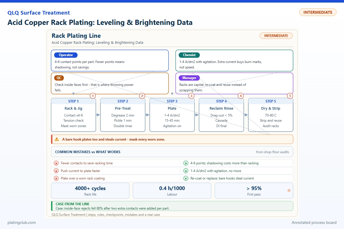
Rack plating / Junior technician / Working data
Acid Copper Rack Plating: Leveling & Brightening Data
A shiny copper surface can still contain deep polishing lines, thin recesses, or poor adhesion. Your job is to separate those faults before making an addition. This guide helps experienced junior technicians control decorative acid copper on racks, compare test pieces, and hand over evidence that the next shift can use.
Use the approved process sheet for your actual additive system. The reference chemistry below is a published supplier example, not a QLQ proprietary formula. Proposed shop alarm limits require engineering approval before becoming production instructions.
1. Separate brightness, leveling, and coverage
Brightness describes reflected light. Leveling describes reduction of an existing surface feature. Coverage means that copper reaches the required locations; throwing power concerns thickness distribution. One result does not prove the others. Keep the same lighting, viewing angle, rack orientation, and inspection locations when comparing parts.
For zinc-alloy bag hardware, confirm that the approved pretreatment and continuous barrier or strike layer are intact before acid copper. Do not place bare zinc die-cast parts directly into this bath. Blisters require investigation of the substrate and preparation sequence, not an automatic brightener correction.
The local QLQ rack-plating note emphasizes clean conductive contacts, part orientation, and solution access. Its additive note provides general management guidance, but does not establish an acid-copper recipe or a verified customer trial. Those gaps must not be filled with invented factory results.
Leveling calculation: L = 100 × (dbefore − dafter) / dbefore.
Here, d is the measured depth of the same groove using a defined reference surface. A reduction from 8 to 3 micrometers gives 62.5% leveling. This is arithmetic illustration, not a measured production result. Use matched grooved coupons; unrelated roughness readings cannot substitute for groove-depth reduction.
2. Working Data & Formula Notes
The following complete make-up example follows the manufacturer's published 120-H system. Retain its named concentrates together: milliliters of one supplier's brightener cannot be exchanged for another supplier's product. Concentrations refer to final solution volume. See the manufacturer's bath composition and operating conditions.
| Component | Range | Typical | Function | Replenishment |
|---|---|---|---|---|
| CuSO4·5H2O | 180–240 g/L | 200 g/L | Copper source | Analyze; reconcile with soluble-anode balance and losses. |
| H2SO4, pure-acid basis | 50–80 g/L | 60 g/L | Conductivity and acidity | Titrate; use an approved correction calculation. |
| Chloride, as Cl− | 60–120 mg/L | 80 mg/L | Additive interaction and anode behavior | Analyze separately; account for water and drag-in. |
| 120-H Mu | 4–6 mL/L | 5 mL/L | Make-up concentrate, including wetting constituents | Supplier-approved analytical or test-panel correction. |
| 120-H A | 0.4–0.6 mL/L | 0.5 mL/L | Leveling-related concentrate | Controlled sample addition, then approved tank dose. |
| 120-H B | 0.4–0.6 mL/L | 0.5 mL/L | Brightening-related concentrate | Validated consumption schedule plus panel confirmation. |
| Deionized water | Balance to final volume | Approved tank working level | Solvent | Restore evaporation losses before final analysis. |
Make-up concentration is not a daily replenishment rate. Calculate additions from verified tank volume and an authorized instruction. Never add concentrates by judging one bright part. Record chemical identity, lot number, measured amount, time, operator, and approving person.
For a mass-based correction, required mass equals concentration deficit multiplied by bath volume. Check units and chemical assay. Chloride is reported as chloride ion, not as grams of sodium chloride or hydrochloric acid; confusing these creates an avoidable overdose.
3. Normal fluctuation bands versus danger thresholds
These are proposed conservative shop controls inside the cited operating envelope, not experimentally established defect-onset boundaries. Enter them on an approved control sheet. Crossing a hold threshold means stop new loads, verify the measurement, and notify the responsible engineer; it does not prove the named defect.
| Parameter | Proposed normal band | Proposed danger / hold threshold | Response and risk |
|---|---|---|---|
| Copper sulfate pentahydrate | 195–215 g/L | <180 or >240 g/L | Repeat analysis; investigate copper balance and thickness distribution. |
| Sulfuric acid | 55–65 g/L | <50 or >80 g/L | Repeat titration; review drag-out and additions. |
| Chloride ion | 75–95 mg/L | <60 or >120 mg/L | Recheck sample and source water; assess anodes and panel response. |
| Temperature | 22–26 °C | <16 or >30 °C | Check independent thermometer and cooling operation. |
| Average cathode current density | 3–4 A/dm2 | <1 or >6 A/dm2 | Verify area and ammeter; inspect recesses and edges. |
| Rack current versus job setpoint | Within ±5% | More than ±10%, or unstable current | Shop-selected electrical alarm; inspect contact resistance. |
| Plating time versus validated cycle | Within ±2% | More than ±5%, or interrupted cycle | Shop-selected timing alarm; segregate affected loads. |
Do not copy a pH 4.2–4.8 window into acid copper. This strongly acidic sulfate bath is controlled by acid analysis, not a mildly acidic pH target. A plausible-looking pH number can conceal a wrong process sheet. Also investigate repeated directional drift within limits rather than waiting for an alarm.
4. Published experimental coupon comparison
The measurements below are from Mariani and colleagues, not QLQ customer batches. Nickel-disc coupons were plated at 25 ± 1 °C, without stirring, at an average 5 A/dm2. Their commercial bath contained 217.2 g/L copper sulfate pentahydrate and 66.1 g/L of 98% sulfuric-acid reagent, with proprietary additives. This differs from the reference formulation above.
| Coupon / comparison | Reported center thickness | Test condition | Interpretation boundary |
|---|---|---|---|
| Sample G | 10.40 ± 0.52 µm | Common conditions above; XRF, 60 s acquisition, 0.6 mm collimator | Highest reported center thickness; not proof of best leveling. |
| Sample H | 5.30 ± 0.27 µm | Same common conditions and XRF method; different current program | Lowest reported center thickness; not a production rejection limit. |
| Study center-thickness average | 8.11 ± 0.41 µm | Study summary, not an additional coupon | Do not treat this as minimum recess thickness. |
The study compared direct, pulsed, and reverse-pulsed current. Its practical lesson is that brightness and uniformity need separate evaluation. Consult the original waveform definitions before interpreting individual sample labels. No salt-spray endurance or plant-specific hardness acceptance is asserted here. Source: Scientific Reports, 12, 18175 (2022).
For production, record coupon identity, substrate, rack position, bath analysis, current, time, and measurement locations. Measure the center, edge, and designated recess independently. Corrosion performance must be qualified on the specified finished multilayer system; isolated copper thickness cannot justify a salt-spray promise.
5. Run a controlled leveling and brightening trial
Take one representative bath sample after circulation. Prepare a retained control and separate trial aliquots using identical coupons. Let the engineer specify additive increments and the laboratory method. Do not return experimental solutions to the production tank.
- Photograph and measure each coupon before plating. Mark the groove and thickness-measurement locations.
- Plate the unchanged control using the approved temperature, agitation, current, and duration.
- Change only one authorized variable in each trial. Keep solution volume and coupon preparation constant.
- Compare brightness under fixed lighting, groove-depth reduction, mapped thickness, and visible defects.
- Repeat the preferred condition on at least three independent coupons as a proposed shop confirmation rule.
- Request approval for any production correction; inspect the first corrected load before releasing further work.
A Hull-cell panel helps compare low- and high-current-density appearance, but its current-density gradient is not a production rack. Use the supplier's panel procedure. If appearance improves while the deepest groove remains, report a brightness improvement only.
Thickness plausibility check: h ≈ 0.220 × J × t × η, with h in micrometers, J in A/dm2, t in minutes, and η as fractional current efficiency.
This Faraday-law calculation uses copper's molar mass, divalent deposition, and density. At 3 A/dm2, 30 minutes, and an assumed 95% efficiency, calculated average thickness is about 18.8 micrometers. It is not measured recess thickness. A major discrepancy calls for checking area, contact, interruptions, and instrument calibration.
6. Two troubleshooting walkthroughs
Bright flat face, visible polishing grooves
This is a diagnostic scenario, not a documented customer case. First compare incoming groove depth and copper thickness against retained acceptable parts. If thickness is short, investigate time and current delivery. If thickness is adequate, conduct the controlled leveling trial. If the control coupon is satisfactory but production parts are not, inspect rack orientation and local solution movement before changing the tank.
Burned edges, dull recessed pockets
This second scenario points toward current distribution or solution access, but chemistry remains a possible contributor. Verify exposed area and actual current, check contacts, and compare opposite rack positions. Trial an engineer-approved orientation or shielding change while keeping chemistry unchanged. A defect that follows rack position is different evidence from one reproduced across the whole laboratory panel. Record what changed, not just “bath adjusted.”
7. Engineer Notes
- Clean and inspect rack tips before loading. Remove damaged racks from service; never rely on a hotter contact to carry the load.
- Calculate current from wetted exposed area, including both plated faces where applicable. Record the area basis beside the setpoint.
- Use a dedicated labeled sampler. Collect after circulation and before dosing; record temperature and sampling time.
- Confirm chemistry before additive trials. Correcting appearance while base analysis is wrong makes the next result harder to interpret.
- Keep anodes, bags, filters, and solution movement on an inspection schedule. Record observed faults rather than making unapproved carbon treatments.
- Handle acid additions only under the approved SOP with cooling, ventilation, chemical-resistant PPE, and eyewash access. Add acid to water, never water to concentrated acid; segregate incompatible wastes.
- Quarantine interrupted or out-of-window loads with traceable rack numbers. Release only after the designated authority accepts the inspection evidence.
8. Shift Checks
| Shift stage | Check item | Frequency | Acceptance standard | Record |
|---|---|---|---|---|
| Before shift | Bath level, temperature, copper, acid, chloride | Start-up; confirm latest approved analysis | Approved normal bands; no unresolved hold | Analysis sheet, analyst, sample time |
| Before shift | Rack contacts, anodes, circulation, extraction | Before first load | Clean intact contacts; equipment operates to SOP | Equipment checklist and rack ID |
| During shift | Current, area basis, cycle time | Every load | Validated job settings and approved tolerances | Load number, amperes, area, minutes |
| During shift | Temperature trend and agitation | Continuous monitoring; hourly logged review | Normal band; no stagnant zones or alarm | Trend log and alarm response |
| During shift | Appearance and mapped thickness | First load, after corrections, then approved sampling | Reference appearance and drawing minima at each location | Photos, readings, disposition |
| After shift | Additions, ampere-hours, held work | At handover | Complete traceability; named owner for unresolved issues | Signed handover and addition log |
Pass criteria belong to the approved drawing and process sheet. An attractive part is not automatically acceptable. Keep rejected samples until the responsible engineer has compared them with the process history.
9. Technician questions to AI
These are representative technician-style prompts, not quotations from verified customer emails.
“AI, my copper is shiny but the polishing lines are still visible. Should I add more brightener?”
Not automatically. Measure incoming groove depth and deposited thickness first. Compare an unchanged sample with an authorized leveling trial. Report brightness and leveling separately, and request approval before tank additions.
“AI, the edges are burning and the recesses are dull. Should I increase the current?”
Increasing current may worsen the edges. Verify exposed area, contacts, orientation, and solution movement. Check bath analysis and compare a laboratory panel. Let the engineer decide whether shielding, agitation, loading, or chemistry needs correction.
“AI, can I use pH to decide how much sulfuric acid to add?”
No. Use the approved acid-analysis method and verified working volume. Record the calculated correction, reagent assay, authorization, and post-mixing confirmation. Do not treat a generic mildly acidic pH range as an acid-copper operating limit.
10. Evidence and the next practical step
Local knowledge-base provenance: QLQ Obsidian Vault, surface-treatment module, “Rack and Barrel Plating” and “Plating Brighteners and Additives” notes, updated July 26, 2026. These support rack-control and additive-management context; detailed acid-copper operating data and a verified QLQ experimental dataset are not available in those notes. Published external sources are linked beside their respective tables.
What Would You Like to Solve?
Send substrate details, layer sequence, additive-system identity, recent analysis, rack area, current, cycle time, and defect photographs to [email protected]. Include the affected location and a retained acceptable sample comparison. For equipment, chemistry, and operator-support planning, see turnkey surface-treatment lines and engineering support. The useful next step is a controlled diagnosis with traceable evidence, not an unexplained chemical addition.