
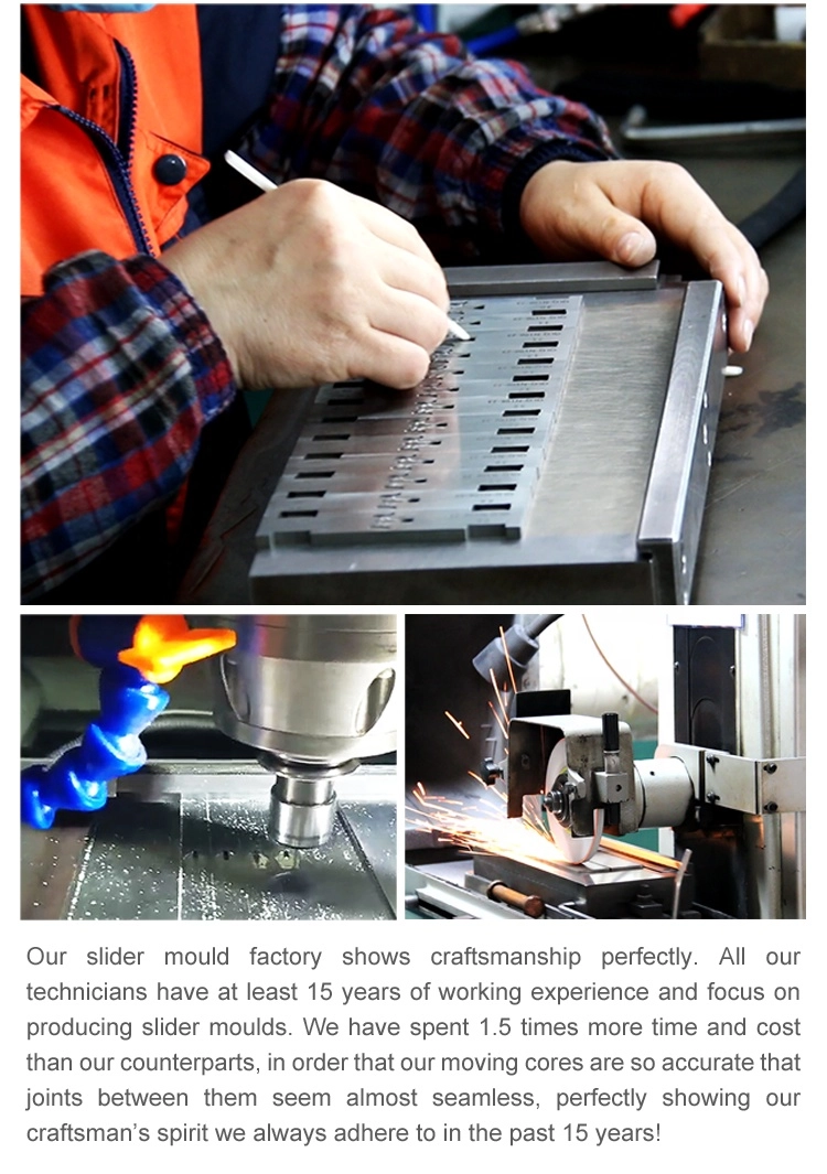
A mould inspection is not a glance; it is a fixed sequence of checks that catch wear before it prints a bad batch. Juniors who inspect honestly protect the tool and the shift.
This guide is the pre-setup inspection sequence for a zinc die-casting mould.
Common Mistakes and How to Avoid Them
The pitfalls that show up most often in real projects, with the cause and the practical fix.
| Mistake | Why It Happens | Practical Fix |
|---|---|---|
| 1. Glance inspection | Wear missed | Follow the checklist |
| 2. Gate never measured | Erosion hidden | Measure at setup |
| 3. Vents assumed clear | Gas burns | Clean and check |
| 4. Ejectors dragging | Marks and sticking | Check and lube |
| 5. Parting burr ignored | Flash grows | Deburr carefully |
| 6. Cooling not verified | Hot spots | Flow check |
| 7. No record | Findings lost | Log the inspection |
| 8. Telling vs showing | No proof | Show the checklist signed |
Best Practices That Hold Up in Production
The operating disciplines that separate a reliable line from a reactive one.
- Follow the fixed checklist
- Measure the gate
- Check vents and ejectors
- Verify cooling flow
- Sign and log
Implementation Roadmap
A practical sequence that can be adapted to your own project.
Process Flowchart
Pre-setup inspection flow
A step-by-step sequence with notes and cautions so every shift follows the same order.
- The gate measurement is the wear alarm.
- Signed inspections are evidence.
- Hot moulds need safe handling.
- Measuring tools need calibration.
Working Data & Formula Notes
Working data - inspection windows
Reference values for zinc die-casting moulds.
| Component / Parameter | Working Value / Role | What Changes Mean (annotation) |
|---|---|---|
| Gate thickness | 0.8-1.2 mm | Below = refurbish. |
| Vent depth | Per design | Too deep flashes. |
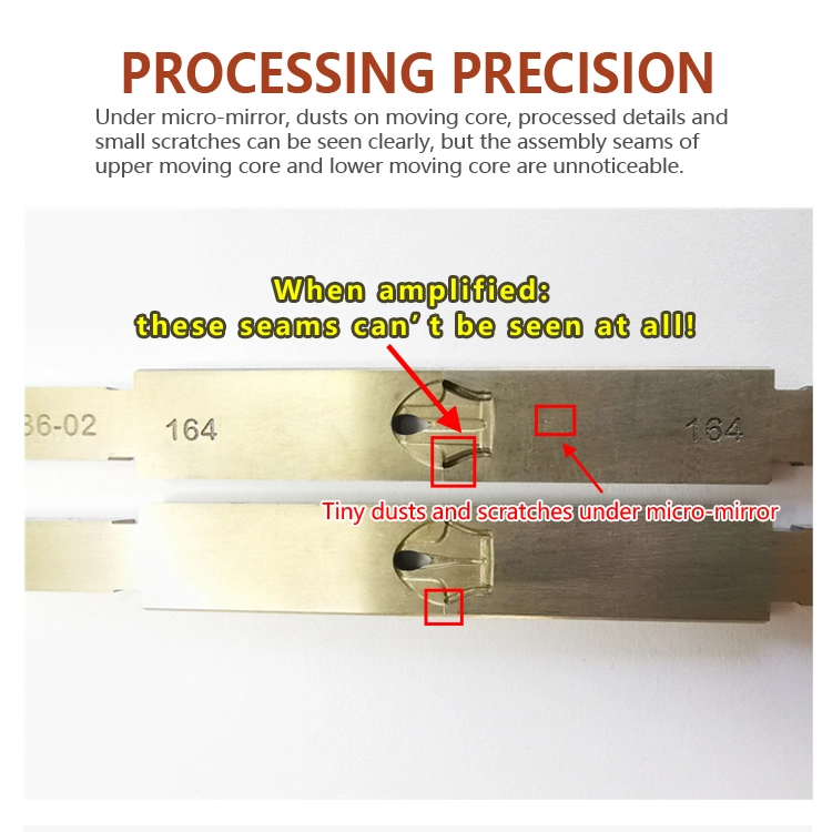
| Cavity accuracy | +/- 0.02 mm | Inspection protects it. |
| Cooling water | 15-25 C | Flow per channel. |
Reference Data
Specifications and references cited in this guide. Confirm final parameters with your line supplier.
Inspection checklist
| Cavity | Gate measure | Vents |
| Ejectors | Parting line | Cooling flow |
| Findings | Actions | Signed |
Implementation Cases
Case 1 - a blocked vent caught at setup
Situation. Gas burns appeared one run; the vent was found blocked.
Approach. The inspection caught it before the shift and the vent was cleaned.
Outcome. No burned parts that day.
Case 2 - gate erosion found by measuring
Situation. Flow marks were intermittent; the gate had never been measured.
Approach. Measuring showed erosion below the window; the gate was refurbished.
Outcome. Flow marks stopped.
Frequently Asked Questions
Why inspect before every setup?
Wear and build-up print into the first parts if unchecked.
Why measure the gate?
Erosion is invisible until it changes the fill.
How do I check vents?
Visual and depth per design; clean if blocked.
What do dragging ejectors do?
They mark parts and stick in the cavity.
Why verify cooling?
A silent channel is a hot spot.
Why sign the inspection?
It is evidence and accountability.
How often calibrate tools?
Per the maintenance schedule; a bad gauge is a bad gate.
What if I find damage?
Stop and call the toolroom - never run a damaged cavity.
What Would You Like to Solve?
Inspect in the fixed order, measure the gate, verify cooling and sign the card. The setup that starts inspected runs clean.
Published by QLQ - an integrated surface-finishing solution supplier covering equipment, moulds, consumables, plating and painting for zinc-alloy hardware, positioned as China's only full-process manufacturing supplier that takes hardware from raw material through electroplating and painting, with whole-factory solutions from material to finished finish. Values cited are project references; confirm with your line supplier before specification.