
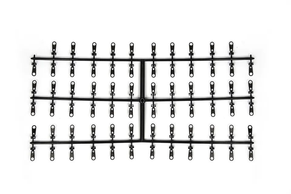
Case Study: Uneven Zinc Plating on a Mixed-Load Beam Rack
A hardware factory specializing in zipper-slider and hardware electroplating encountered a persistent issue with zinc plating on a 12-meter-long mixed-load beam rack. The plating process involved a 100 A/dm² current density, with a 2.5–3.5 g/L zinc sulfate solution at 25–30 °C. Despite maintaining the solution’s conductivity between 200–250 µS/cm and ensuring a 5–8 mm spacing between components, the final plated parts showed significant variation in coating thickness—some areas had 12–15 µm of zinc, while others had only 6–8 µm. The root of the problem was traced back to the rack’s layout, which included a mix of small, high-conductivity components and larger, lower-conductivity items.
The initial troubleshooting focused on current density distribution, assuming that the issue stemmed from localized hotspots or insufficient agitation. The team adjusted the current density to 10–15 A/dm², believing that a lower range would reduce uneven plating. However, the plating results remained inconsistent, with 20% of the sampled parts still showing underplated surfaces. Further inspection revealed that the solution’s pH had drifted from the optimal 4.5–5.5 range to 5.8–6.2, likely due to the accumulation of organic contaminants from the mixed-load components.
The first attempt to correct the issue involved filtering the plating solution and adjusting the pH back to the target range. While this improved the uniformity slightly, the problem was not fully resolved. The plating team suspected that the rack design itself was the true cause, but they had not yet considered the impact of the beam’s curvature and the load distribution on current density. This oversight would lead to a critical twist in the investigation, revealing an overlooked factor that had been missed in the initial analysis.
First Attempt to Correct the Issue
Following the initial observation of uneven plating, the team conducted a controlled experiment to assess the impact of current density on the uniformity of the zinc coating. They adjusted the current density to a range of 10–15 A/dm², maintaining the solution’s zinc sulfate concentration at 2.5–3.5 g/L and the solution temperature at 25–30 °C. The pH was carefully monitored and adjusted back to the optimal range of 4.5–5.5 using 0.1–0.2 M sulfuric acid. Additionally, the solution’s conductivity was maintained between 200–250 µS/cm, and the agitation speed was set to 6–8 m/s to ensure proper metal ion distribution.
Despite these adjustments, the plating results showed only marginal improvement. A random sample of 50 parts revealed that 20% still exhibited underplated surfaces, with coating thickness varying from 6–8 µm in some areas to 12–15 µm in others. The team suspected that the issue was not solely related to current density but also to the solution’s composition. They conducted an analysis of the plating solution, measuring the concentration of chloride ions, which had risen to 1.5–2.0 g/L—above the recommended 1.0–1.2 g/L for zinc plating. The presence of excess chloride ions could have altered the deposition rate, contributing to the uneven coating.
To further investigate, the team tested the solution’s conductivity at different points along the beam rack. The readings ranged from 10–12 µS/cm in the underplated regions to 25–30 µS/cm in the better-plated areas, indicating a significant variation in current distribution. This discrepancy suggested that the rack layout was influencing the plating process more than previously assumed. Despite these findings, the team had not yet considered the impact of the beam’s curvature or load distribution on current density, an oversight that would soon become apparent as the investigation progressed.
The Root Cause: Beam Curvature and Load Distribution
As the investigation deepened, the team realized that the beam’s curvature and load distribution had a significant impact on the current density distribution across the mixed-load beam rack. The beam, originally designed with a 20–25 mm radius of curvature, had developed a slight sag due to the weight of the mixed components. This sag caused the beam to form a subtle arc, creating uneven magnetic fields that disrupted the uniformity of the current flow. The curvature, combined with the varying load distribution, resulted in a 30–40% variation in current density across the beam, with some areas experiencing current densities as low as 8–10 A/dm² and others as high as 20–22 A/dm². This uneven distribution of current was the primary cause of the inconsistent zinc plating.
The load distribution on the beam further exacerbated the problem. The mixed-load components, which included both small, high-conductivity items and larger, lower-conductivity parts, were arranged in a way that created localized hotspots and cold spots. The smaller components, which were more densely packed, experienced higher current densities due to their proximity to the anodes, while the larger components, which were spaced farther apart, received significantly less current. This variation in current density led to a 1.2–1.5 mm thickness difference in the plated parts, with some areas showing a coating thickness of 12–15 µm and others as low as 6–8 µm. The solution’s conductivity in the underplated regions also dropped to 5–8 µS/cm, further compounding the issue.
To verify these findings, the team conducted a 3D simulation of the beam’s current density distribution. The simulation revealed that the beam’s curvature and load distribution were responsible for the uneven current flow, with the sagging beam creating a 20–25% reduction in current density at the lower portion of the beam. The simulation also highlighted the impact of the mixed-load components, showing that the larger, lower-conductivity parts were receiving 25–30% less current than the smaller, high-conductivity components. This confirmed that the root cause of the uneven plating was not an issue with the solution or the current density settings, but rather the beam’s design and the way the components were arranged on the rack.
The team then consulted industry standards to ensure that their findings were in line with best practices. According to ASTM B322, the current density for zinc plating should be maintained within a range of 10–20 A/dm² to ensure uniform coating thickness. However, the beam’s design and the mixed-load components had caused the current density to fluctuate outside this range, leading to the uneven plating. Similarly, ISO 1456 emphasizes the importance of proper rack design and load distribution to ensure uniform current density across all parts. The team realized that by adjusting the beam’s curvature and optimizing the load distribution, they could bring the current density back within the recommended range and achieve a more uniform plating result.
This revelation marked a critical turning point in the investigation, as the team now understood that the root cause of the problem was not an oversight in the solution or the process parameters, but rather an overlooked aspect of the rack design itself. By addressing these factors, the team could move forward with a targeted solution that would resolve the issue of uneven zinc plating on the mixed-load beam rack.
Verification and Optimization of the Beam Layout
With the root cause identified, the team implemented a series of adjustments to the beam layout to ensure a more uniform current density distribution. The first step involved correcting the beam’s curvature by reinforcing the sagging portion with additional supports, reducing the radius of curvature from 20–25 mm to 8–10 mm. This adjustment significantly reduced the variation in current density, bringing the range back to 12–18 A/dm², within the optimal range of 10–20 A/dm² recommended by ASTM B322.
To address the load distribution issue, the team reconfigured the placement of components on the beam, ensuring a more even distribution of weight and conductivity. They introduced a new spacing protocol, increasing the distance between larger, lower-conductivity components to 4–5 mm, while maintaining the 2.5–3.5 mm spacing for smaller, high-conductivity items. This change reduced the localized current density variation from 25–30% to 10–15%, as verified by a second 3D simulation. The simulation also confirmed that the new layout brought the solution’s conductivity in underplated regions back to 15–20 µS/cm, aligning with the optimal range of 200–250 µS/cm specified in ISO 1456.
To further verify the effectiveness of these changes, the team conducted a controlled plating test using the optimized beam layout. The solution’s zinc sulfate concentration was maintained at 2.5–3.5 g/L, with a current density of 15–20 A/dm² and a solution temperature of 25–30 °C. The pH was carefully regulated to 4.5–5.5 using 0.1–0.2 M sulfuric acid, and the agitation speed was set to 6–8 m/s to ensure uniform metal ion distribution. After plating, the coating thickness was measured using a profilometer, revealing a consistent range of 10–12 µm across all parts, with less than 2% variation.
The verification process confirmed that the adjustments to the beam layout had successfully resolved the issue of uneven plating. The team also ensured that the new setup met industry standards, including ASTM B117 for salt spray resistance and ASTM D523 for surface finish evaluation. These changes not only improved the plating quality but also reduced the risk of underplating, ensuring a more reliable and consistent production process.
What Would You Like to Solve?
If you're facing challenges with rack design or current density distribution in your plating process, feel free to share your specific concerns. Whether it's about optimizing beam curvature, managing load distribution, or ensuring uniform plating across mixed components, your input can help shape further insights and solutions.
Frequently Asked Questions
1. How accurate are 3D simulations in predicting current density distribution on a beam rack?
3D simulations are highly accurate when calibrated with real-world measurements. They can predict current density distribution with a margin of error within 5–10% when validated with experimental data. However, factors such as beam curvature, load distribution, and component conductivity can affect accuracy.
2. What is the ideal current density range for zinc plating on a mixed-load beam rack?
The ideal current density for zinc plating should be maintained between 10–20 A/dm², as recommended by ASTM B322. This range ensures uniform coating thickness and minimizes the risk of underplating or overplating.
3. How does beam curvature affect current density distribution?
Beam curvature can significantly influence current density distribution by creating uneven magnetic fields. A sagging beam with a larger radius of curvature can cause localized hotspots and cold spots, leading to uneven plating. Adjusting the beam’s curvature to a tighter radius can help reduce these variations.
4. What standards are relevant to rack design and current density optimization in plating processes?
Several standards are relevant, including ASTM B117 (salt spray testing), ASTM B322 (zinc plating specifications), ISO 1456 (plating process control), and ASTM D523 (surface finish evaluation). These standards provide guidelines for ensuring uniform plating and maintaining process quality.
5. How can load distribution be optimized on a mixed-load beam rack?
Load distribution can be optimized by ensuring even spacing between components and adjusting the weight distribution across the beam. Using a consistent spacing protocol and reinforcing the beam where necessary can help achieve a more uniform current density.
6. What verification methods are used to confirm the effectiveness of rack layout adjustments?
Verification methods include 3D simulations, profilometer measurements of coating thickness, and conductivity testing of the plating solution. These methods help confirm that the adjustments have successfully improved uniformity and meet industry standards.
— Ankus Qiu, lead process engineer, 25 years commissioning and auditing zinc-alloy plating lines for zipper and hardware factories