
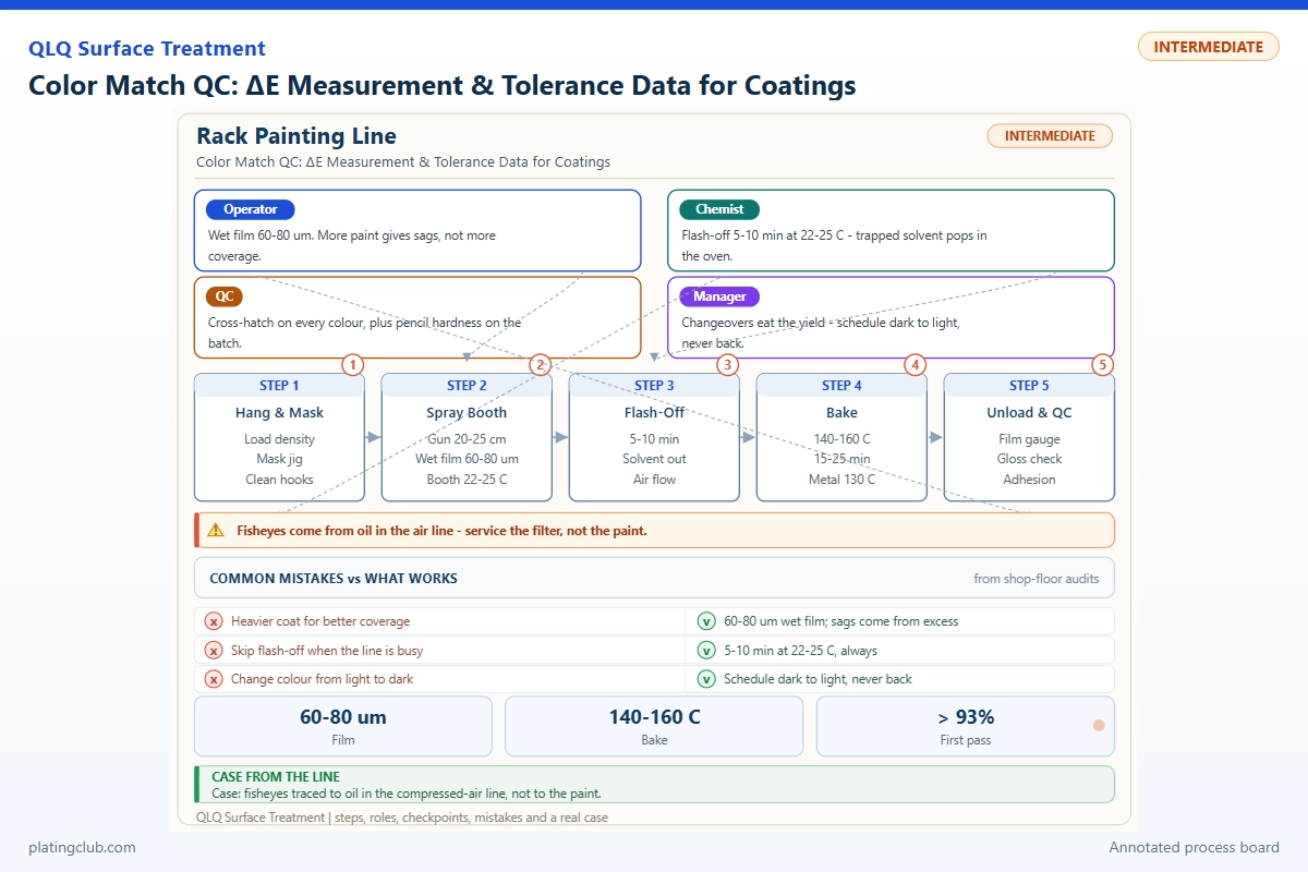
Color Match QC: ΔE Measurement & Tolerance Data for Coatings
A management-level color system must distinguish pigment mismatch from application drift, measurement error and customer acceptance. For painted zinc-alloy bag hardware, zipper sliders and related metal components, one green instrument result cannot replace control of film thickness, surface appearance, adhesion and corrosion resistance.
1. Define the acceptance contract before measuring
Specify the master panel, coating system, substrate, pretreatment, primer, measurement geometry, aperture, illuminant, observer and color-difference equation. Identify whether the customer accepts an opaque solid finish or a metallic, pearlescent or translucent finish. These are different measurement problems.
ΔE is a distance, not a diagnosis. Retain signed ΔL*, Δa* and Δb*: positive values indicate lighter, redder and yellower samples respectively. CIELAB distance is ΔE*ab = √[(ΔL*)² + (Δa*)² + (Δb*)²]. For an illustrative change of +0.6, −0.3 and +0.4, ΔE*ab is 0.78. This is not automatically ΔE00.
CIEDE2000 applies perceptual weighting and interaction terms. Use validated instrument software and record its parameter settings; do not substitute the simple CIELAB equation. Different equations produce different acceptance outcomes. X-Rite's color-tolerancing explanation describes why perceptual tolerance shapes differ from simple coordinate boxes.
As an illustrative negotiated policy for an opaque solid finish, investigate above ΔE00 0.8 and hold above 1.2. Those numbers are proposed management limits, not industry-wide requirements. Agree them using physical boundary samples, assembly viewing and customer approval. A threshold appropriate for a pale neutral may be inappropriate for a textured dark finish.
2. Make the measurement system repeatable
For the example workflow, use d/8 geometry, SCI, D65 illumination, the 10° observer and CIEDE2000 with kL = kC = kH = 1. Use the same UV setting and an aperture fully covered by the sample. SCI includes specular reflection and reduces surface-gloss influence; SCE excludes it and is more appearance-sensitive. Neither mode is interchangeable with the other. See Konica Minolta's SCI/SCE guidance.
Calibrate according to the instrument manual. Then measure a stable verification tile independent of the calibration standard. Take five lift-and-reposition readings at marked locations, recording the mean and maximum difference from the master. Keep panel orientation, backing, cooling time and measurement age fixed. Do not select only the most favorable location.
On narrow or curved hardware, build a locating fixture and check aperture coverage. A flat witness panel tracks process conditions but does not prove the actual component matches: edge build, recesses and tumbling exposure can differ. Measure representative parts wherever geometry permits and approve an assembly-level visual method where it does not.
Before setting a tight tolerance, run a practical measurement study: three operators, ten representative panels and three repositioned readings per panel. Estimate instrument, positioning and operator contributions. Metallic finishes require multi-angle evaluation rather than this single-angle solid-color protocol; BYK's multi-angle instrument documentation illustrates that distinction.
3. Working Data & Formula Notes
The following complete 100 kg formulation is an engineering starting-point example for a white, one-component waterborne acrylic topcoat over a validated primer. It is not a QLQ commercial formula or a verified production recipe. Qualify compatibility, hiding, adhesion, storage stability and durability before use. Supplier formulations and technical data take precedence.
| Component | Range | Typical | Function | Replenishment |
|---|---|---|---|---|
| Acrylic emulsion, 45% solids | 50–60 | 55.00 | Film-forming binder; 24.75 kg dry polymer | Restore only through an approved balanced blend |
| Rutile titanium dioxide | 15–22 | 18.00 | White opacity and scattering | Use a qualified grind; never add dry powder to the spray tank |
| Compatible aqueous tint dispersion | 0–2 | 1.00 | Sets undertone; fixed pigment identity and strength | Weigh approved concentrate after a laboratory match |
| Deionized water | Balance to 100 | 20.20 | Carrier and application adjustment | Restore measured loss; verify solids and viscosity |
| Compatible coalescent | 1.5–4 | 3.00 | Supports film formation | Only against the approved mass balance |
| Polymeric dispersant, 40% active | 0.4–1.2 | 0.80 | Stabilizes the pigment grind | Adjust in the grind after compatibility testing |
| Substrate-wetting additive | 0.1–0.4 | 0.30 | Promotes continuous wetting | Small weighed additions after a crater/wetting trial |
| Defoamer | 0.1–0.5 | 0.30 | Controls entrained air | Split additions; verify no cratering |
| HEUR rheology modifier, 20% active | 0.1–0.6 | 0.30 | Controls flow and sag | Predilute as specified; allow viscosity equilibration |
| Supplier-approved neutralizer solution | 0.05–0.2 | 0.10 | Adjusts pH within binder limits | Titrate a retained sample before tank addition |
| Total | 100 | 100.00 | Balanced wet formulation | Recalculate every authorized change |
The ranges are development windows, not simultaneous allowable batch deviations. Changing one component requires rebalancing water and reviewing pigment-to-binder ratio. This example contains approximately 12% coalescent on dry binder; actual demand depends on resin and drying conditions. It does not use a hardener or a two-component pot life.
Prepare the pigment grind separately, disperse to a qualified endpoint, then add emulsion under controlled lower shear. Add compatible letdown ingredients and adjust water last. The dispersant example contains 0.32 kg active material, about 1.8% on titanium dioxide; colored pigments may need very different levels. BYK's technical guidance explains pigment-dependent dispersant demand. Dow's industrial acrylic selector provides supplier context, not validation of this example.
For correction, m = M × r: a screened addition ratio of 0.0005 to a 200 kg batch means 0.10 kg concentrate. Validate that ratio on a retained sample, spray and dry it, then approve scale-up. Never infer tint dosage from ΔE alone.
4. Experimental batch comparison and release evidence
No traceable QLQ experimental batch dataset was available for this topic. The values below are explicitly illustrative training data, not measured results, customer cases or performance guarantees. Use the table as a laboratory recording template and replace every result before qualification.
| Panel/batch | Dry film, μm | Mean / maximum ΔE00 | 60° gloss, GU | Pencil hardness | 48 h NSS observation | Test condition |
|---|---|---|---|---|---|---|
| R: reference application | 25 | 0.35 / 0.45 | 72 | H | No blistering; 0.5 mm mean scribe creep | Primer-coated zinc-alloy panels; seven-day ambient drying |
| T: deliberately thin | 16 | 1.42 / 1.65 | 69 | H | Localized blistering; 1.6 mm mean creep | Same substrate, primer, paint lot and drying; lower spray deposition |
| W: water over-adjustment | 22 | 0.92 / 1.13 | 61 | HB | Localized blistering; 1.2 mm mean creep | Additional 3 kg water per original 100 kg; deposition not compensated |
| C: screened tint correction | 25 | 0.48 / 0.59 | 71 | H | No blistering; 0.6 mm mean creep | Approved laboratory tint adjustment; reference application restored |
Common example conditions: seven days at 23 ± 2°C and 50 ± 5% RH; color measured after conditioning under the specified SCI protocol. Hardness follows the laboratory's controlled pencil-test procedure. NSS uses 5% sodium chloride at 35°C, with sealed edges and a defined scribe. Record actual chamber conditions, replicate results and photographs.
The QLQ knowledge-base note “Salt Spray Testing” lists 48 hours as a general spray-coating benchmark. Exposure time alone is not a pass criterion. Agree blistering, corrosion, scribe-creep limits and substrate-specific assessment with the customer. Salt fog does not predict field lifetime, and a color pass cannot override a durability failure.
5. Trend bands versus danger thresholds
These are proposed pilot-line controls for this example, not universal specifications. Validate each band against the selected coating's data sheet. Values between the normal band and hold threshold trigger investigation; missing or unreliable measurements also block release.
| Parameter | Normal fluctuation band | Danger / hold threshold | Required response |
|---|---|---|---|
| Individual-location ΔE00 | 0–0.8 | >1.2, subject to customer agreement | Contain affected lots; check method before tinting |
| Dry film thickness | 23–28 μm | <20 or >32 μm | Check deposition, hiding and actual-part geometry |
| Application viscosity, DIN 4 cup at 23°C | 25–30 s | <22 or >34 s | Verify temperature and solids; correct by approved procedure |
| Waterborne paint pH | 8.0–8.8, if binder-approved | <7.5 or >9.2 | Investigate stability; isolate before adjustment |
| Paint temperature | 21–25°C | <18 or >30°C | Condition paint; repeat viscosity measurement |
| 60° gloss | 68–76 GU | <63 or >81 GU | Check atomization, drying and surface texture |
| Gun distance, selected rack-spray setup | 180–220 mm | <150 or >300 mm | Reset fixture/robot position; verify witness panel |
| Repositioning repeatability, ΔE00 spread | ≤0.15 | >0.30 | Stop color decisions; inspect fixture and instrument |
Chart signed color coordinates as well as ΔE. A steady movement toward yellow can warrant action before the distance limit is exceeded. Establish statistical control limits from a stable process; do not call the customer tolerance a three-sigma control limit. Track first-pass approval, correction mass, rework hours and customer escapes without widening specifications to improve reported yield.
6. Engineer Notes
- Store the master in a dark protective sleeve. Assign revision, approval date and replacement rules; compare working standards against the protected master.
- Mark panel orientation and five measurement positions. Exclude edges only by a documented method, not after seeing unfavorable readings.
- Check film thickness and gloss before adding tint. Restore spray deposition if the panel lacks hiding; do not compensate translucency by recoloring the paint.
- Retain samples before and after every correction. Record concentrate lot, scale identification, addition mass, mixer time and approving engineer.
- Compare under D65 and the customer-agreed secondary light source. Quarantine a metameric mismatch even when D65 ΔE passes.
- For baked coatings, log actual part-metal temperature and time, not just oven air setpoint. The ambient-dry example above must not inherit a baking schedule from another resin.
- Keep rejected material physically identified. Release only after repeat testing and independent quality authorization; commercial urgency is not a technical deviation approval.
7. Shift Checks and accountable handover
| Shift stage | Check item | Frequency | Acceptance criterion | Record |
|---|---|---|---|---|
| Before shift | Instrument and verification tile | Start; after relocation | Manufacturer calibration plus validated tile limits | Instrument ID, tile reading, operator |
| Before shift | Master revision; paint identity | Every job change | Approved revision and correct batch; no unauthorized blend | Job traveler and paint lot |
| Before shift | pH, viscosity, temperature; first-off panel | Each tank and setup | Pilot bands; color and appearance approved | Tank log and first-off signature |
| During shift | Color, thickness and gloss | Hourly; after refill or adjustment | All locations meet approved limits | Panel map, raw readings, process settings |
| During shift | Drying/cure and visual match | Every lot; after interruption | Qualified schedule and agreed lighting approval | Drying profile and visual decision |
| After shift | Retains, held lots and correction balance | Every handover | Traceable samples; all holds identified | Hold register and incoming supervisor signature |
| After shift | Durability-test status | Each qualification or scheduled audit | Required results complete before applicable release | Laboratory report linked to coating lot |
8. Two diagnostic implementation scenarios
These are hypothetical training scenarios, not documented customer outcomes. They apply the knowledge-base troubleshooting sequence without inventing customers or savings.
Scenario A: pale hardware shifts after a refill
A rack-spray supervisor sees increasing ΔL* on pale zinc-alloy pulls. Contain production since the last verified sample, compare retained paints at equal thickness, then inspect refill mixing and solids. If controlled panels match but line panels do not, investigate deposition and hiding. Verify recovery on consecutive samples and actual parts before releasing the hold.
Scenario B: instrument passes, assembled parts disagree
Dark slider bodies and pull tabs show a visual mismatch while SCI readings pass. Compare gloss, texture and SCE diagnostics without changing the contractual measurement method. Examine differing drying exposure and part orientation. If pigment correction would spoil the SCI match, address appearance instead. Obtain approved assembly boundary samples and document the additional visual criterion.
9. Technician-to-AI FAQ
The following are representative technician prompts, not quotations from recorded customer conversations.
“AI, our ΔE00 is 0.7, but the customer says the parts look different. What should I check first?”
Confirm master revision, geometry, SCI/SCE mode and viewing illumination. Then compare gloss, texture, thickness and assembly orientation. Check a secondary light source for metamerism. Do not argue from one number: the agreed acceptance contract may include appearance criteria beyond color distance.
“AI, can I fix a yellow shift by adding blue tint directly into the production tank?”
Not without a screened trial. Confirm measurement repeatability, drying history and the retained batch at reference thickness. Weigh a qualified tint into a laboratory sample, apply and dry it, then evaluate all signed coordinates, gloss and compatibility. Scale only an approved correction and retain both versions.
“AI, how do I choose a ΔE limit that operators can actually maintain?”
Start with customer-approved boundary panels and a measurement study. Demonstrate stable capability across paint lots, operators and line conditions. Set an internal warning below the shipment limit and assign a hold response. If capability is inadequate, improve the process or negotiate the finish specification explicitly; never silently relax the limit.
10. What Would You Like to Solve?
Send the substrate, coating and primer identities, master revision, measurement settings, raw color coordinates, thickness, gloss and drying history to [email protected]. QLQ can help structure a reproducible investigation spanning preparation, application and inspection. For wider line coordination, see surface-treatment lines, equipment, chemicals and technical support.
Knowledge-base grounding: QLQ local notes “Painting Process,” “Painting Defect Analysis” and “Salt Spray Testing,” respectively in 02-Product-Knowledge/07-Surface-Treatment and IMA Company Knowledge, note 067 (English labels for the local source files). These support the process context and troubleshooting sequence, not the illustrative formulation, batch results or proposed tolerance bands. Confirm current supplier instructions and the customer's test agreement before implementation.