
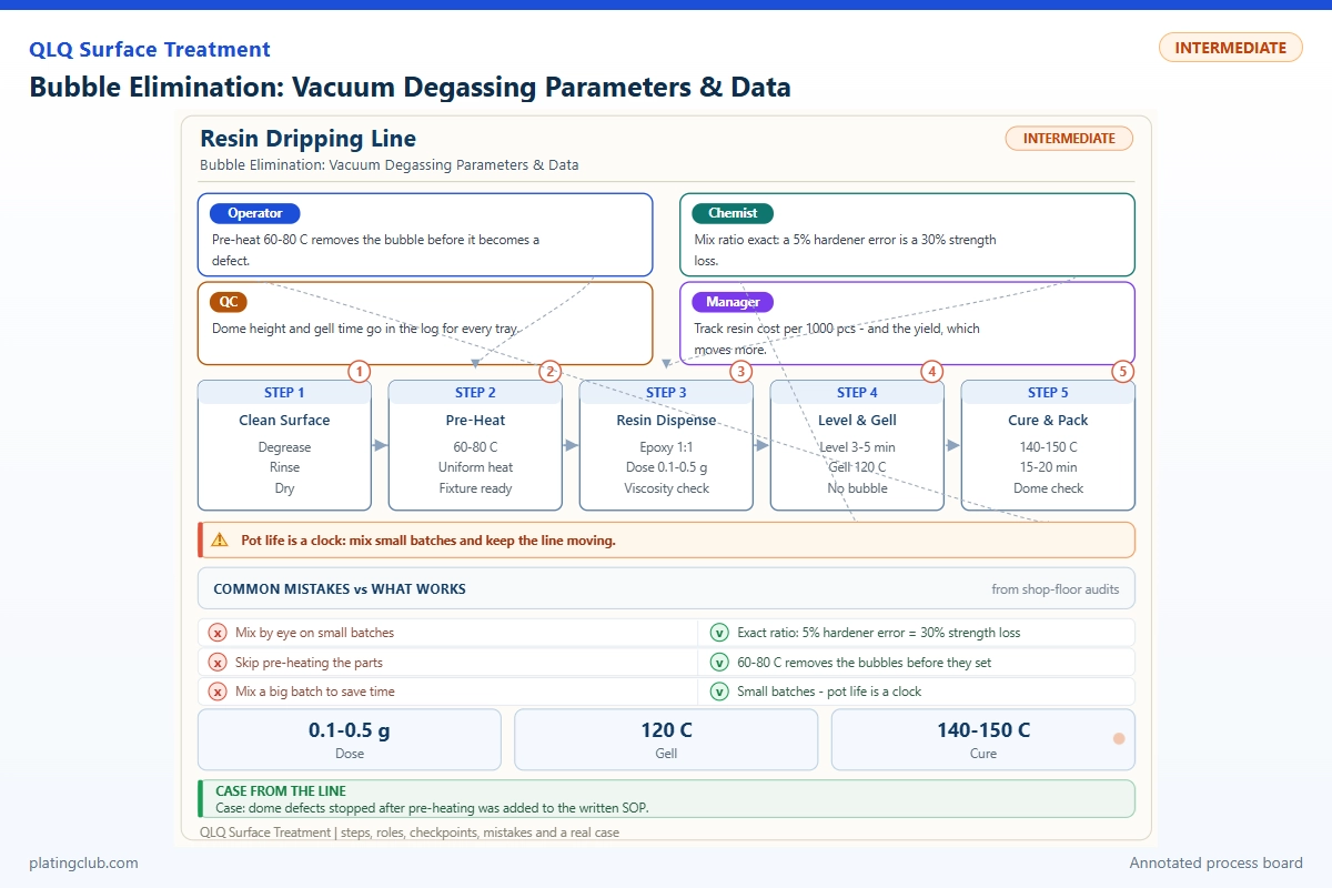
Bubble Elimination: Vacuum Degassing Parameters & Data
For management-level resin-dripping teams, bubble control is a coordinated system: material selection, metering, vacuum performance, dispensing, substrate preparation and cure. A clear mixing cup does not prove that a plated badge, recessed puller or decorative insert will cure without voids.
This guide focuses on solvent-free, two-component epoxy trials on finished metal hardware. Silicone, polyurethane and PVC plastisol require separate recipes and qualification. No QLQ customer degassing test report was available in the reviewed knowledge base; published reference measurements and proposed factory trial settings are therefore identified separately.
Measure pressure
Absolute kPa, not an unexplained negative gauge number.
Protect working time
Count from first resin–hardener contact.
Release by evidence
Pressure trace, witness specimens and batch identity.
1. Identify the Bubble Source Before Increasing Vacuum
Mixing introduces air; leaking suction fittings introduce more during dispensing. Recesses trap air beneath a flowing dome. Moisture or residual cleaner can generate bubbles during cure. These mechanisms require different corrective actions: stronger vacuum cannot repair contaminated components, poor wetting or an off-ratio mixture.
Crosslink Technology describes both trapped air and reaction-generated gas, and warns that prolonged evacuation can remove formulation volatiles. Its guidance emphasizes low viscosity, shallow material depth and avoiding turbulence. Those principles support the diagnostic sequence below, but do not establish a universal cycle for every decorative resin. Source: Crosslink Technology, Degassing Materials.
| Observation | Isolation test | Corrective decision |
|---|---|---|
| Bubbles already visible in the cup | Compare gentle mixing with the current mixer, using identical mass and temperature. | Remove the vortex; validate vacuum with a shallow charge. |
| Cup clear; nozzle stream cloudy | Collect first-shot and steady-flow samples in transparent cups. | Inspect suction seals, feed level, mixer installation and refill technique. |
| Bubbles concentrated at cavity corners | Dispense into flat witnesses and actual recessed hardware. | Change the fill path and examine surface cleanliness. |
| Bubbles appear only during cure | Compare cleaned, fully dried hardware with the existing preparation route. | Investigate outgassing, moisture and cure temperature before extending vacuum. |
2. Working Data & Formula Notes
A complete commercial two-component system is preferable to an improvised additive package. The following unfilled benchmark uses WEST SYSTEM 105 resin and 207 hardener; it is a reference mixture, not a qualified QLQ doming product. Obtain approval for plated-metal adhesion, dome shape, yellowing and service exposure before production.
| Component | Range | Typical | Function | Replenishment |
|---|---|---|---|---|
| 105 epoxy resin | 100 parts, fixed basis | 100.00 parts | Film-forming matrix | Meter fresh resin into each new batch. |
| 207 matched hardener | 24.04–29.33 parts; supplier's published ratio envelope | 27.47 parts | Crosslinking component | Meter fresh hardener; never top up reacted material. |
| Solvent, pigment, filler or additional defoamer | 0 parts in this benchmark | 0 parts | Excluded to isolate processing effects | No additions without separate supplier approval and qualification. |
The published mass ratio is 3.64:1, with an acceptable envelope of 3.41:1–4.16:1. The hardener quantities above are calculated as 100 divided by that ratio. The volume ratio is different: 3:1. Source: WEST SYSTEM technical data sheet, 105/207, page 3.
For a proposed 100 g trial, weigh 78.45 g resin and 21.55 g hardener. Use a verified balance with 0.01 g readability for this scale. The broad published envelope is not the shop's routine metering tolerance. Center the process on the nominal ratio, and use a tighter internal action limit after weighing uncertainty is evaluated.
Mixed resin has no bath-style replenishment strategy. Adding fresh hardener to an aging cup creates uncertain reaction history. Discard expired mixtures according to the SDS and local waste procedure. Refill unmixed reservoirs separately, retaining component lot numbers and closing containers promptly.
3. Vacuum Parameters: Pressure, Geometry and Time
Use Pabsolute = Patmospheric − vacuum depression. At 101.3 kPa atmospheric pressure, 29 inHg vacuum depression is approximately 3.1 kPa absolute. At altitude, the same gauge reading may be unattainable; absolute pressure makes recipes transferable between factories.
As a first approximation, an existing air bubble expands in volume by Pinitial/Pfinal at constant temperature. From 101.3 to 4 kPa, that factor is about 25.3. Real foam also depends on viscosity, surface tension and gas release; this calculation is not a cup-capacity specification.
Smooth-On's chamber instructions describe evacuation near 29 inHg, watching foam rise and collapse, then waiting about 60 seconds before venting. This is equipment guidance, not a validated epoxy recipe. Follow the chamber's temperature and cleaning restrictions. Source: Smooth-On, 5 Gallon Vacuum Chamber Instructions.
For the proposed small epoxy trial, begin with a shallow charge in a cup filled to no more than one quarter of its capacity. Throttle evacuation when foam approaches the rim. Record time to pressure, foam-collapse time and temperature at removal. Start a 60–90 second post-collapse hold only if the remaining working time permits. Vent gradually and dispense promptly with minimal free fall.
4. Normal Fluctuation Bands Versus Danger Thresholds
These are proposed commissioning limits for the small benchmark trial, not universal material specifications. Replace them with demonstrated limits after capability studies. Never transfer epoxy values directly to silicone, polyurethane or PVC.
| Parameter | Proposed normal band | Danger threshold / action limit | Required action |
|---|---|---|---|
| Chamber pressure during stable hold | 3–5 kPa absolute | >8 kPa after evacuation stabilizes; persistent boiling at any pressure | Hold batch; check leakage or volatile loss. |
| Component temperature before mixing | 22–25°C | <18°C or >30°C | Condition closed components; reassess viscosity and working time. |
| Post-collapse hold | 60–90 seconds | >120 seconds without an approved cycle | Review temperature and remaining dispense time. |
| Resin:hardener mass ratio | 3.60:1–3.68:1 internal target | Outside target: hold; outside supplier envelope: reject | Verify metering; do not correct an aging cup. |
| Cup fill before evacuation | 15–25% of cup capacity | >25% or foam near suction port | Split unmixed charges; throttle or safely vent. |
| Age at final dispensing | At most 40% of demonstrated usable life | >50% or visible thickening | Stop dispensing and segregate affected parts. |
| Empty-chamber pressure rise, isolated for 60 seconds | At most 1 kPa above baseline | >2 kPa or sustained deterioration | Investigate seal, valve and fittings before processing. |
| Witness dome thickness | 0.80 ± 0.10 mm, proposed trial target | <0.60 or >1.00 mm | Check dispense mass and geometry; hold trial comparison. |
Trend pressure rise, cycle time and defect rate together. A drifting cycle can reflect leakage, colder resin or increasing batch depth. Do not normalize a deteriorating process by repeatedly widening its limits.
5. Experimental Data and the Factory Comparison Plan
The table below contains published comparative material measurements, not vacuum-treated versus untreated QLQ batches. It establishes realistic viscosity and hardness magnitudes; it cannot demonstrate that degassing improves hardness or salt-spray life.
| Specimen system | Mixed viscosity | Pot life | Cured hardness | Test condition |
|---|---|---|---|---|
| 105/205 | 975 mPa·s | 9–12 min | 83 Shore D | Viscosity: ASTM D2393 at 72°F; pot life: 100 g at 72°F; hardness: ASTM D2240. |
| 105/206 | 725 mPa·s | 20–25 min | 83 Shore D | Same published viscosity and pot-life conditions; cured hardness conditioning not specified. |
| 105/207 | 760 mPa·s | 22–26 min | 84.4 Shore D | Same published viscosity and pot-life conditions; cured hardness conditioning not specified. |
Source: WEST SYSTEM combined technical data sheet, pages 1–3, dated October 2014. Confirm current regional documentation before adopting the reference chemistry.
Run three independent matched batch pairs. In each pair, keep resin lots, ratio, preparation, mixing and cure constant; compare no vacuum with the proposed cycle. Use ten actual hardware pieces per condition, plus suitable witness specimens. Alternate processing order to reduce time-of-day bias.
| Batch / specimen | Treatment | Thickness | Bubble result | Hardness / durability | Test condition |
|---|---|---|---|---|---|
| Pairs 1–3, control | Gentle mixing, no vacuum | Target 0.80 ± 0.10 mm; measured value pending | Count and maximum diameter pending | Shore D and adhesion pending; salt spray not tested | Same plated lot; documented cure; inspect at 10× after cure. |
| Pairs 1–3, vacuum | Proposed 3–5 kPa absolute cycle | Same target; measured value pending | Count and maximum diameter pending | Same tests; results pending | Matched witnesses; record temperature, pressure trace and cycle timestamps. |
Define a bubble, inspection area and customer acceptance limit before testing. Report defects per inspected piece and voids per unit area separately. Measure Shore D on suitable molded witnesses, not a thin dome over metal. If corrosion testing is required, specify substrate, plating stack, exposed edges, method and failure criterion; no salt-spray hours can be inferred from a bubble count.
6. Two Diagnostic Implementation Scenarios
Recessed plated badge: A proposed investigation compares flat witnesses with deep corner features. If witnesses remain clear but corners contain voids, change to a one-direction fill path and inspect wetting. Confirm the change on actual geometry. This is a diagnostic scenario, not a documented customer success claim.
Multi-nozzle dripping cell: A second proposed investigation separates mixing from transfer. Collect samples before the hose and after each nozzle following refill and steady operation. A nozzle-specific defect points toward seals, mixer setup or cavitation. Assign maintenance ownership rather than extending every batch's vacuum time. No measured improvement is claimed.
7. Engineer Notes
- Verify the absolute-pressure sensor against a reference; label gauge and absolute instruments unmistakably.
- Weigh components separately and reconcile both masses with the batch sheet before mixing.
- Scrape cup walls and base gently; transfer to a clean cup when required by the approved mixing method.
- Keep the charge shallow, watch foam continuously and prevent resin entering the pump inlet.
- Leak-test the empty chamber; never diagnose leakage from a bubbling resin charge alone.
- Inspect pump oil, trap and exhaust routing. Use vacuum-rated equipment, guarding and SDS-selected protection; never improvise a pressure vessel.
- Retain labeled witness specimens and quarantine parts when pressure, ratio or mixture age breaches the action limit.
8. Shift Checks and Management Ownership
| Shift stage | Check item | Frequency | Acceptance standard | Record |
|---|---|---|---|---|
| Before shift | Chamber, seal, trap, sensor | Every shift and after maintenance | No damage; empty-chamber rise meets approved limit. | Equipment checklist and pressure trace |
| Before shift | Material identity and balance | Each component lot and shift | Matched approved components; verification weight passes site tolerance. | Lot register and balance log |
| During shift | Ratio, temperature, pressure, mixture age | Every batch | All inside approved operating bands. | Timestamped batch traveler |
| During shift | Nozzle stream and witness appearance | Startup, refill and every batch | No persistent stream aeration; qualified visual limit met. | Sample ID and defect photographs |
| After shift | Yield, scrap, exceptions and maintenance | Every shift | All exceptions dispositioned; suspect stock segregated. | Supervisor handover and corrective-action log |
Track first-pass yield, vacuum-cycle minutes, discarded mixed mass and rework by defect source. Qualify changes across operators and representative ambient conditions. A faster cycle is valuable only when downstream rejects remain controlled.
9. Technician Questions to AI
These are suggested troubleshooting prompts, not verbatim customer correspondence.
“AI, our resin keeps bubbling under vacuum. Should I leave it in longer?”
Not automatically. Check absolute pressure, charge temperature, foam behavior and usable-life budget. Persistent bubbling may be volatile loss or contamination rather than trapped air. Isolate the material lot, compare a fresh sample and seek supplier guidance before extending the cycle.
“AI, the cup is clear but bubbles appear on plated pullers. What should I check first?”
Sample the nozzle stream, then compare flat witnesses with actual puller recesses. Inspect suction leaks, refill aeration, trapped corner air and residual cleaner. Use matched prepared parts to isolate substrate outgassing; change one variable at a time.
“AI, can I add extra hardener or thinner to speed up bubble removal?”
No unapproved additions. Extra hardener changes stoichiometry; thinner can alter cure, safety and volatile release. Restore the correct ratio, condition unmixed components and reduce charge depth. Any additive requires supplier approval and separate adhesion, appearance and durability qualification.
10. What Would You Like to Solve?
Send your resin TDS, hardware geometry, plating stack, batch mass, pressure trace and defect photographs to [email protected]. Review the integrated equipment, chemistry and process-support scope when coordinating upstream cleaning and downstream dripping.
The QLQ knowledge-base source Machine Directory — Page 25 (source title translated into English; updated August 11, 2026) lists QLQ-LSMM liquid-silicone mixing, QLQ-LSVM vacuum and QLQ-12LSDM dispensing equipment. It does not establish epoxy compatibility or the operating limits above. Confirm configuration and material suitability before specifying equipment.