
Sharp edges plate badly: current density concentrates, the nickel burns and the corner rejects. Edge rounding is not cosmetic, it is a plating preparation step.
This intermediate guide covers how to control edge radius on belt and buff machines, measure it, and stop the polishing step from changing part dimensions.
Common Mistakes and How to Avoid Them
The pitfalls that show up most often in real projects, with the cause and the practical fix.
| Mistake | Why It Happens | Practical Fix |
|---|---|---|
| 1. Soft wheel on cut stage | Radius grows beyond spec | Hard wheel holds the edge |
| 2. Radius never measured | Drift found only at plating | Gauge first piece and mid-run |
| 3. Over-polish corners | Radius 0.8 mm +, weak latch | Stop at spec, not at gloss |
| 4. Different operators | Radius varies by person | Fixed pass sequence and time |
| 5. Pressure too high | Flats and radius growth | Light passes, more strokes |
| 6. Belt worn uneven | One side rounds more | Change belt on schedule |
| 7. No gauge on line | Guesswork radius | Radius gauge at every station |
| 8. Radius treated as cosmetic | Plating burn returns | Log radius with the job card |
Best Practices That Hold Up in Production
The operating disciplines that separate a reliable line from a reactive one.
- Set a radius target per part drawing
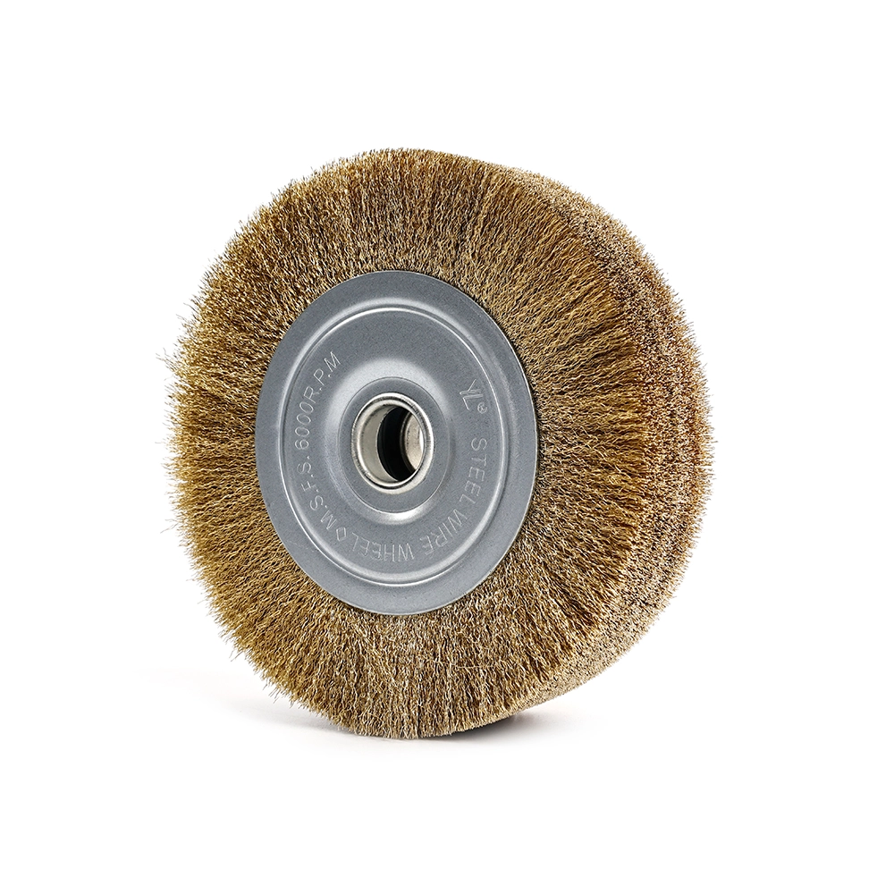
- Use the hardest wheel that still cuts cleanly
- Measure the first piece and every 200 pieces
- Keep the same pass sequence for every operator
- Record radius on the job card with the gloss result
Implementation Roadmap
A practical sequence that can be adapted to your own project.
Process Flowchart
Radius control flow
A step-by-step sequence with notes and cautions so every shift follows the same order.
- Radius is a plating preparation step, not decoration.
- More light strokes hold the edge better than pressure.
- Radius gauges need calibration.
- Do not chase gloss at the cost of radius.
Working Data & Formula Notes
Edge radius data
Reference values for zinc alloy hardware before plating.
| Component / Parameter | Working Value / Role | What Changes Mean (annotation) |
|---|---|---|
| Edge radius | 0.2-0.4 mm | Below burns, above weakens features |
| Contact wheel | 80-90 Shore A cut stage | Soft wheels grow the radius |
| Check interval | First piece + every 200 | Drift found early is cheap |
| Pass pressure | Light, repeat strokes | High pressure flattens and rounds |
Reference Data
Specifications and references cited in this guide. Confirm final parameters with your line supplier.
Radius vs plating result
| Radius | Typical result |
| < 0.15 mm | Nickel burn on corners |
| 0.2-0.4 mm | Clean coverage, no burn |
| > 0.6 mm | Weak latch / visible rounding |
Implementation Cases
Case 1 - latch corners burning in nickel
Situation. Bag locks rejected for burnt nickel on the latch corners; the radius was under 0.1 mm from an aggressive belt cut.
Approach. The cut stage was moved to a hard contact wheel with light passes, and a radius gauge check was added to the first piece.
Outcome. Radius held at 0.25-0.35 mm and the corner burn disappeared in the first plating batch.
Case 2 - operator-to-operator radius drift
Situation. A zipper accessory line had the same drawing but three different edge looks depending on who polished.
Approach. A fixed pass sequence with timed strokes was posted at the station and the speed was locked; mid-run radius checks every 200 pieces were enforced.
Outcome. Radius variation dropped to +/-0.05 mm and plating rejects from edges fell sharply.
Frequently Asked Questions
Why do sharp edges burn in plating?
Current concentrates on sharp corners, raising local current density and burning the deposit.
What is the right radius for bag hardware?
Usually 0.2-0.4 mm; confirm against the part drawing and plating trial.
Which wheel holds edges?
Hard contact wheels (80-90 Shore A) hold edges; soft wheels round them.
How often measure radius?
First piece and every 200 pieces, plus after any belt or wheel change.
Can pressure be used to round edges?
Pressure rounds fast but flattens flats; light repeated strokes are safer.
What if radius grows beyond spec?
Reduce passes and check wheel hardness; re-work the affected batch before plating.
Does radius affect gloss?
Yes - deeper radius usually means softer cut, which can lower gloss; balance both.
Who should approve the radius target?
Engineering together with plating, because the radius is a plating input.
What tool measures 0.2-0.4 mm?
A radius gauge set or profile comparator with 0.05 mm resolution.
What Would You Like to Solve?
Send us your part drawing with the radius call-out and the plating defect photo. We can help set the wheel, pass sequence and check interval for your line.
Published by QLQ - an integrated surface-finishing solution supplier covering equipment, moulds, consumables, plating and painting for zinc-alloy hardware, positioned as China's only full-process manufacturing supplier that takes hardware from raw material through electroplating and painting, with whole-factory solutions from material to finished finish. Values cited are project references; confirm with your line supplier before specification.