
BARREL PLATING / INTERMEDIATE TECHNICIAN WORKING GUIDE
Vibration Finishing Interface: Pre-Plate Surface Prep Data
A smooth zinc-alloy slider can still carry abrasive fines, compound residue and trapped liquid into a plating barrel. Control the handover between vibratory finishing and pretreatment as a measurable process, not a visual approval. This guide helps experienced technicians separate preparation defects from nickel-bath and barrel-contact problems.
Scope and Evidence Status
The route considered is zinc-alloy bag hardware: vibratory finishing, media separation, cleaning, rinsing, approved activation and compatible strike/undercoat, followed by barrel nickel plating. Nickel must not be deposited directly on bare zinc using the reference Watts bath below. Confirm the complete substrate-specific route with the process owner.
QLQ knowledge-base notes support vibratory finishing for small hardware and identify cleaning as essential to adhesion. They do not provide a measured finishing-versus-corrosion trial for this article. Consequently, the experimental values below are synthetic training data, not measured results, customer cases or performance promises. Proposed interface limits are commissioning targets requiring local validation; the cited Watts composition is an industry reference.
Define the Interface Before Changing the Bath
Create one traveler joining casting lot, finishing machine, media code, compound lot, cycle time, cleaning tank and plating barrel. Record media age and fines removal as well as part mass. A nominal bowl volume is not its approved usable load, and a plating barrel's kilogram capacity does not establish its electrical contact quality.
The QLQ-SSL-8.2 vibrating-machine note describes an approximately 25–30-minute polishing stage after an earlier polishing operation. Treat that as a source-specific sequence, not a universal cycle. Different burr size, casting porosity, media shape and surface specification require different trials.
Release the handover only when three checks agree: geometry is acceptable, recesses are free of lodged media, and cleaned parts pass the agreed cleanliness test. Use low-magnification inspection around holes and puller pockets. Measure roughness on the same accessible face and direction every time. A bright appearance cannot establish freedom from organic film.
Wet finishing chemistry also matters: compounds help transport removed metal and media debris out of the process. This role is described by Rösler's compound guidance. A blocked drain or ineffective solids separation can defeat an otherwise correct cycle.
Working Data & Formula Notes
Use the downstream nickel bath as a controlled reference while investigating preparation. The table gives a complete additive-free Watts base electrolyte, not a proprietary bright-nickel package or a finishing-compound recipe. Published base ranges come from the Nickel Institute Nickel Plating Handbook. Typical values are selected mid-range trial setpoints.
| Component | Range | Typical | Function | Replenishment |
|---|---|---|---|---|
| Nickel sulfate hexahydrate, NiSO4·6H2O | 240–300 g/L | 270 g/L | Main nickel-ion supply | Analyze nickel; consider anode dissolution and drag-out before calculated additions. |
| Nickel chloride hexahydrate, NiCl2·6H2O | 30–90 g/L | 60 g/L | Supports conductivity and anode dissolution | Analyze chloride independently; do not infer deficiency from nickel alone. |
| Boric acid, H3BO3 | 30–45 g/L | 40 g/L | Buffers conditions near the cathode | Restore from analysis using approved dissolution practice. |
| Deionized water | Balance to final volume | 1 L final solution | Solvent | Restore level after evaporation; distinguish water loss from solution drag-out. |
The handbook describes general Watts operation at pH 3.5–4.5 and 40–60°C. These are not automatic barrel-production settings. The narrower control bands in the next section are proposed for a local trial. Commercial wetters and brighteners require the supplier's own concentrations and analysis; adding an unspecified package invalidates this additive-free comparison.
Calculate a salt correction as addition, kg = concentration deficit, g/L × working volume, L ÷ 1,000. A verified 10 g/L deficit in a 1,000 L tank therefore requires 10 kg of the stated salt, before any purity correction. If analysis reports elemental nickel instead, convert to the appropriate hydrate basis first. Keep analytical corrections separate from rectifier ampere-hour records.
Normal Fluctuation Bands and Action Thresholds
These are proposed trial guardrails, not universal defect boundaries. Approve them against the drawing, supplier instructions and a known-good run. Crossing an action threshold means hold, investigate and document; it does not prove a particular defect mechanism.
| Parameter | Proposed normal band | Danger / hold threshold | Action and interpretation |
|---|---|---|---|
| Final vibratory stage | 25–30 min for the cited sequence | Outside the qualified cycle | Inspect burrs and dimensions; extra time can remove useful material. |
| Ra on designated face | 0.25–0.50 µm trial target | >0.80 µm or >25% drift from baseline | Check media wear and incoming casting; low Ra alone is insufficient. |
| Metered compound feed | 90–110% of qualified rate | <80% or >120% | Verify actual delivery; the wrong dose can leave dirt or persistent residue. |
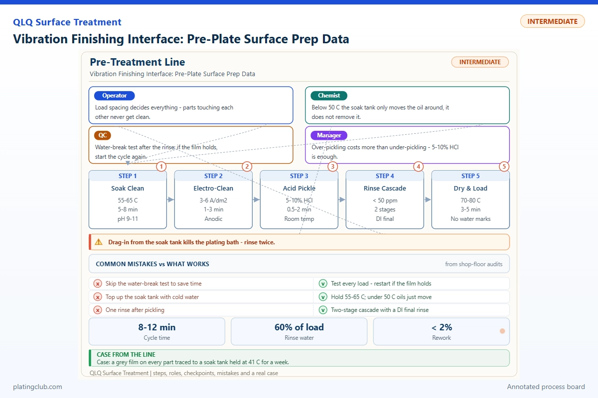
| Post-cleaning water film | Continuous film for 30 s in the local check | Any visible early break | Hold affected parts; recheck cleaner and rinses rather than adding brightener. |
| Final pretreatment rinse conductivity | ≤100 µS/cm at 25°C, provisional | >200 µS/cm or twice validated baseline | Restore rinse exchange; conductivity does not measure all organic contamination. |
| Watts nickel pH | 4.0–4.4 selected trial band | <3.5 or >4.5 | Confirm sample temperature and calibration before approved correction. |
| Watts nickel temperature | 50–55°C selected trial band | <45°C or >60°C | Check probe and circulation; hold until the qualified window is restored. |
| Plating barrel part mass | 95–105% of validated reference load | <90% or >110% | Reweigh and inspect turnover; mass changes contact and solution access. |
Plot readings by lot and shift, not just daily averages. Three consecutive movements toward a limit deserve investigation even before the limit is crossed. Mark media replacement, compound changes, rinse renewals and analytical additions on the same chart to expose cause-and-effect timing.
Experimental Comparison: Separate Smoothness from Cleanliness
Split one casting lot into three preparation groups. Repeat each group in three independent barrel loads with randomized run order. Use production parts plus representative coupons, retaining identical undercoat, nickel chemistry, part load, electrical recipe and sealing condition. Coupons cannot reproduce every contact and recess effect on actual hardware.
| Group / preparation | Ra, µm | Water-film check | Nickel thickness, µm | Blistered parts | Test condition |
|---|---|---|---|---|---|
| A: 25 min finishing; standard cleaning | 0.46 ± 0.06 | 10/10 pass | 8.2 ± 0.7 | 0/30 | Three loads; 10 parts/load; designated face; XRF at three marked sites; approved local adhesion screen. |
| B: 30 min finishing; deliberately insufficient cleaning in isolated trial | 0.31 ± 0.05 | 4/10 pass | 8.1 ± 0.8 | 7/30 | Same lot and plating recipe as A; same XRF sites and adhesion procedure; no production release. |
| C: 30 min finishing; restored cleaning and rinse exchange | 0.32 ± 0.04 | 10/10 pass | 8.3 ± 0.6 | 0/30 | Same lot and plating recipe as A; identical sampling; corrective preparation only. |
Values are invented for training; ± denotes illustrative sample standard deviation. The adhesion procedure and acceptance criterion must be written before a real trial. For XRF, calibrate for the actual substrate and multilayer stack; incorrect layer assumptions can distort thickness readings.
This example demonstrates why matching thickness does not establish matching adhesion. Group B is smoother but less clean. A real conclusion requires replicate-load results, inspection evidence and approved testing. Do not report salt-spray hours or coating hardness without measurements. If corrosion testing is specified, record exposure method, duration, seal cure, evaluated area and failure definition; do not convert chamber hours into service life.
Two Troubleshooting Scenarios to Reproduce Locally
Scenario 1: Clean faces, blistered puller pockets
On zinc-alloy slider bodies, inspect pockets immediately after media separation and again after cleaning. Photograph residue and collect rinse liquid from the recesses. Compare the approved cleaning cycle with improved solution access, holding finishing and plating constant. If pocket cleanliness improves but blistering remains, examine casting porosity and activation. This is a diagnostic scenario, not a documented customer outcome.
Scenario 2: Thin recessed areas after a load increase
On small bag fittings, mark exposed and recessed measurement sites. Compare the validated barrel load with the increased load using the same preparation. Record turnover, current interruptions and site-specific thickness rather than one average. If a return to the reference load restores the thickness distribution while cleanliness remains unchanged, investigate contact and transport before altering finishing compound. Do not claim success until independent repeat loads confirm it.
Engineer Notes
- Measure actual feed: collect compound delivery into a graduated vessel for a timed interval, calculate the rate and compare with the pump setting.
- Check media lodging: sieve the working media and inspect the smallest openings on ten representative parts before releasing a new media batch.
- Sample before activation: perform the local water-film check after cleaning and rinsing. Reclean sampled parts through the approved route before plating.
- Trace debris: collect bowl discharge and final-rinse samples in labeled containers. Compare settled solids and filter residues with the known-good baseline.
- Separate corrections: change only one preparation factor per trial. Hold barrel load and bath composition steady to avoid confounded conclusions.
- Protect the surface: prohibit bare-hand contact and use clean transfer containers. If the approved transfer interval is exceeded, follow the validated recovery route.
- Close the loop: quarantine suspect lots, record the last acceptable traveler and approve release only after repeated acceptable loads and documented inspection.
Shift Checks
| Shift stage | Check item | Frequency | Acceptance standard | Record |
|---|---|---|---|---|
| Before shift | Media, separator and drain | Once; repeat after media change | Correct media; no blocked drain or lodged particles in sample | Media code, sieve result, operator |
| Before shift | Compound feed and cleaner analysis | Start-up | Qualified feed band; cleaner within supplier-approved analysis range | Measured rate, titration, correction |
| During shift | Cycle, load and transfer interval | Every lot | Approved traveler settings; no unexplained waiting | Lot mass, start/end times, barrel ID |
| During shift | Water film, recess cleanliness, rinse conductivity | First lot, then hourly | No film breaks or retained debris; validated conductivity limit | Sample IDs, temperature, readings |
| During shift | Nickel pH, temperature and thickness sites | pH/temperature hourly; thickness per approved sampling plan | Qualified bath window; drawing minimum at each required site | Probe status, XRF calibration, site results |
| After shift | Rejects, trends and handover | Every shift end | All suspect lots identified; open deviations assigned | Hold list, charts, next-shift actions |
Technician Questions to Ask an AI Assistant
These are example prompts, not quotations from customer records. Supply your actual observations before accepting a diagnosis.
"My parts look brighter after vibration finishing, but nickel still blisters. What should I check first?"
Start with recess debris, compound removal and the post-cleaning water-film result. Compare affected and unaffected parts from the same lot. Then verify the approved activation and strike route, followed by casting integrity. A shiny surface cannot rule out contamination, and thicker nickel will not repair an unbonded interface.
"Can I add more brightener when the barrel batch comes out dull after polishing?"
Not without evidence. First verify whether the issue follows a finishing lot or every barrel. Check cleanliness, temperature, pH, loading and contact. Run the supplier-approved bath diagnostic only after confirming those conditions. Uncontrolled additions may obscure the original cause and make later recovery harder.
"How do I prove the new finishing cycle is better without changing the whole plating line?"
Split one casting lot, randomize matched barrel runs and change one preparation variable. Compare roughness, water-film checks, dimensional loss, site-specific thickness and approved adhesion results. Repeat independent loads. Include corrosion testing only when required and keep sealing identical. Retain raw records, including failures, rather than reporting only favorable averages.
Source Notes and Release Boundary
Local QLQ sources: QLQ-Obsidian-Vault/03-Equipment Knowledge/Three-Piece Slider Equipment/QLQ-SSL-8.2 Vibrating Type Polishing Machine (200L); Surface Treatment Process / Polishing Equipment; Surface Treatment Process / Rack and Barrel Plating; Surface Treatment Process / Cleaning and Sealing. Topic labels are English translations of local note titles. These sources support equipment context and workflow, not the synthetic experimental values or proposed control thresholds.
Before adopting this card, the responsible engineer must approve the complete zinc-alloy pretreatment route, chemical compatibility, test procedures and release limits. Use current supplier safety data and site controls for nickel salts, acids and cleaning chemicals. Segregate incompatible waste streams and do not discharge untreated process liquid.
What Would You Like to Solve?
Send the alloy, part photograph, media specification, finishing cycle, cleaner analysis, barrel load and marked thickness results. Include the location and timing of blistering or dullness. Review the integrated surface-treatment line, equipment and chemistry support approach when the defect crosses equipment boundaries. For an engineering review of your preparation-to-plating interface, email [email protected].