
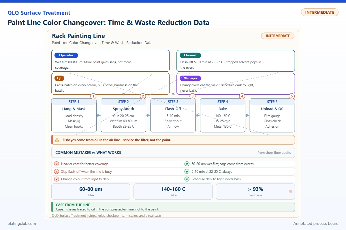
Paint Line Color Changeover: Time & Waste Reduction Data
For intermediate technicians in plating and surface-treatment factories, a successful color change ends with an accepted coating, not merely a clean-looking hose. The practical objective is to shorten last-good-part to first-good-part time while reducing discarded paint and flushing liquid without increasing contamination, thin coverage, or curing defects.
Evidence Boundary and Process Scope
The QLQ knowledge base describes lacquer coating of zipper sliders and zinc-alloy hardware, but contains no verified color-change trial dataset or customer-specific savings report. Numerical comparisons below are explicitly illustrative training data, not measured QLQ results. Replace them with signed production records before using them in a customer claim or investment calculation.
This article separates oven-cured hardware lacquer from a published two-component polyurethane mixing example. Their recipes and cure schedules are not interchangeable. The coating supplier's approved technical data sheet, substrate preparation specification, equipment manual, and customer acceptance criteria override every proposed trial limit here.
1. Locate the Waste Before Shortening the Purge
Divide changeover into paint recovery, isolation, cleaning, next-color charging, spraying adjustment, and acceptance. Record timestamps at each boundary. A shorter cleaning stage is meaningless if operators then spend longer correcting shade or waiting for another cured sample.
Identify every wetted section: tank outlet, suction tube, pump, filter bowl, regulator, color valve, hose, and gun. A valve pocket or filter containing previous-color pigment can contaminate a seemingly clear flush. Measure system hold-up rather than assuming hose length alone represents the whole circuit.
For a cylindrical hose, volume in milliliters equals 0.7854 × internal diameter squared in millimeters × length in meters. A 6 mm bore, 10 m hose holds about 283 mL; reducing its length to 4 m lowers hose inventory to about 113 mL. The 170 mL difference is geometric capacity, not guaranteed paint savings: fittings, circulation paths, and the release endpoint still matter.
Graco describes placing the mixing point closer to applicators and using equipment-controlled flushing sequences to reduce waste. Treat those principles as design options, not instructions to retrofit an unapproved air-pulse sequence. See the manufacturer's color-change explanation.
2. Working Data & Formula Notes
A complete shop-floor formulation can mean a complete ready-to-apply mixture of supplied coating components; it need not disclose a proprietary resin-manufacturing recipe. The example below uses Jotun Hardtop XP solely because its component ratio is publicly documented. It is not a QLQ lacquer recipe or a validated coating for zinc-alloy sliders.
| Component | Range | Typical | Function | Replenishment |
|---|---|---|---|---|
| Hardtop XP Component A | Fixed 10 parts; no discretionary ratio range | 10.0 L | Supplied pigmented base containing the coating's formulated constituents | Prepare a fresh complete batch; never top up mixed paint with base alone. |
| Hardtop XP Component B | Fixed 1 part per 10 parts A | 1.0 L | Specified curing component | Measure with A at the same approved ratio; do not add extra hardener to accelerate cure. |
| Jotun Thinner No. 63, optional | 0–5% maximum addition under the cited sheet; confirm the supplier's percentage basis | 0 L unless specifically approved | Supplier-listed option for faster curing; reduces pot life | Only a measured, authorized addition. Never use thinner to revive expired mixed paint. |
The unthinned example totals 11 L. There are no separate shop additions of pigment, resin, silicone, or catalyst. Use a smaller batch when demand cannot consume 11 L within the applicable pot life. The Jotun technical data sheet specifies the 10:1 ratio and thinner limitations; confirm the applicable regional version before use.
For the factory's oven-cured lacquer, obtain its own base, reducer, and hardener instructions. Do not substitute the polyurethane ratio or bake it at the lacquer temperature. Solvent choice must also match seals and equipment. Separate cleaning-fluid replenishment from coating formulation: track fresh cleaner, recovered cleaner, and dirty waste independently.
3. Normal Bands Versus Stop-and-Investigate Thresholds
QLQ's general painting note gives 0.2–0.4 MPa gun pressure, 150–300 mm distance, and 15–30 micrometers coating thickness. Its barrel-painting note gives 15–25 seconds in a Tu-4 cup and 30–45% drum loading. These are reference envelopes, not proof that one coating works throughout every range.
The narrower bands below are proposed commissioning targets for a selected oven-cured lacquer trial, not universal danger limits. Validate them against an accepted reference batch; measure air pressure with the gun flowing and viscosity at a controlled temperature.
| Parameter | Normal fluctuation band | Danger / hold threshold | Technician response |
|---|---|---|---|
| Tu-4 efflux time at 25°C | 18–22 s | Below 15 or above 25 s | Hold; verify temperature and supplier-approved reduction. |
| Gun inlet air pressure, flowing | 0.25–0.35 MPa | Below 0.20 or above 0.40 MPa for this selected setup | Check regulator, restrictions, and atomization; respect gun rating. |
| Gun-to-work distance | 180–220 mm | Below 150 or above 300 mm | Restore fixture position; inspect coverage and dry spray. |
| Dry-film thickness | 20–25 µm | Below 15 or above 30 µm | Quarantine trial output; check flow and passes. |
| Barrel loading by usable volume | 35–40% | Below 30 or above 45% | Restore qualified load; inspect exposed and contact surfaces. |
| Color difference, ΔE00 | 0–0.8 against approved master | Above 1.0, proposed trial limit | Hold; verify master, cure, thickness, and instrument settings. |
Do not assign a universal pH limit to solventborne lacquer. Likewise, the knowledge-base bake envelope of 120–180°C is not a recipe. Set the actual part-metal temperature and dwell from the selected coating's qualification, then monitor oven loading and a recorded temperature profile.
4. Controlled Trial: Time, Waste, and Coating Quality
Run matched baseline and revised changes for the same difficult transition, such as black to white. Use the same coating batches, hardware preparation, operator, load, and approved bake profile. Repeat each method at least three times, retaining individual readings instead of reporting only the best cycle.
| Batch / method | Test condition | Changeover | Flush / discarded paint | DFT | ΔE00 | Pencil hardness | Salt-spray observation |
|---|---|---|---|---|---|---|---|
| A: timed baseline | Black→white; identical prepared zinc-alloy coupons; qualified lacquer cure; evaluation after 7 days at 23°C | 22 min | 2.4 L / 0.60 L | 23 µm | 0.6 | H | At 96 h: no blistering on unscribed face |
| B: shorter wetted path plus verified cleaning endpoint | Same coupons, lacquer lots, load, cure, and conditioning as A | 14 min | 1.5 L / 0.35 L | 24 µm | 0.7 | H | At 96 h: no blistering on unscribed face |
| C: prematurely stopped cleaning | Same conditions as A; purge stopped before validated endpoint | 10 min initially; rejected | 1.0 L / 0.25 L before rework | 22 µm | 2.1 | H | Not tested; color rejection prevents release |
In a real trial, document thickness measurement method, substrate corrections, pencil procedure, instrument geometry, and replicate count. Define salt-spray solution, chamber settings, coupon orientation, scribing, edge protection, and corrosion-rating method in the test plan. “No blistering at 96 hours” alone neither proves corrosion compliance nor predicts service life.
For the illustrative A-to-B comparison, time reduction is (22 − 14)/22 × 100 = 36.4%; flush reduction is 37.5%; discarded-paint reduction is 41.7%. At eight changes per shift, the arithmetic gives 64 minutes, 7.2 L flush liquid, and 2.0 L paint avoided. These are demonstration calculations, not a factory forecast. Count rework and waiting before declaring a gain.
5. Two Worked Troubleshooting Scenarios
Scenario A: Black residue appears only after restarting
This is a diagnostic example, not a documented customer case. The last flush sample looks clear, but white parts become gray after several minutes. Check valve branches, the filter housing, and low-flow pockets rather than repeatedly extending the main-hose purge. Under the prescribed safe isolation procedure, inspect these locations and confirm every relevant flow path receives cleaning.
Repeat a controlled flush, then collect initial and delayed next-color samples. Record sample volume and time. If contamination returns after a dwell, investigate retained pigment or valve leakage. Do not release production solely because the first sprayed card passed.
Scenario B: Matching shade but different hardness
This second diagnostic example concerns an approved two-component system. Color matches, but the first post-change batch remains softer than the reference. Check proportioner calibration, mixed-material age, residual cleaner, and substrate temperature. A longer color purge cannot correct a wrong component ratio.
Segregate suspect parts, verify component delivery according to the equipment procedure, and prepare a fresh correctly proportioned sample. Compare after identical conditioning. Preserve the failed sample and batch record; do not add hardener or extend an arbitrary bake to hide the defect.
6. Engineer Notes
- Label every hose and valve branch on a wetted-path sketch. Measure hold-up after any plumbing change and revise the qualified cleaning recipe.
- Plan compatible colors from light to dark where scheduling allows, but retain a separately validated dark-to-light cleaning sequence.
- Collect recoverable unmixed paint separately from dirty cleaner. Return it only through an approved traceable procedure; never return mixed two-component waste.
- Use numbered sample containers at fixed cleaning stages. Compare the endpoint under consistent lighting; confirm next-color quality with an approved master.
- Before flushing, disable electrostatics, follow pressure-relief instructions, verify extraction, and use approved grounded collection equipment. Never spray cleaner into the room.
- Use air/solvent chopping only when the installed equipment manual authorizes it. Graco describes programmed alternation on supported systems, not a universal manual technique: flushing-process documentation.
- Change one variable per trial. Require supervisor approval and acceptable first-batch evidence before saving a revised recipe.
7. Shift Checks
| Shift stage | Check item | Frequency | Acceptance criterion | Record |
|---|---|---|---|---|
| Before shift | Extraction, grounding, interlocks, collection vessels | At startup and after maintenance | All prescribed checks pass; no bypass or leak | Safety checklist and operator signature |
| Before shift | Material identity, ratio, expiry, master panel | Each prepared batch | Correct approved materials and recipe revision | Lot numbers, quantities, mixing timestamp |
| During shift | Viscosity, flowing pressure, gun position | Startup, each change, then hourly | Within qualified recipe bands | Readings, liquid temperature, adjustments |
| During shift | Cleaning endpoint and delayed color sample | Every color change | Validated endpoint; next-color sample accepted | Sample IDs, waste volumes, timestamps |
| During shift | Film thickness, shade, cure evidence | First batch after change; approved sampling thereafter | Product specification met; suspect output held | Panel readings and release signature |
| After shift | Waste reconciliation and equipment shutdown | Every shift end | Streams labeled; amounts reconciled; prescribed shutdown complete | Waste log, defect log, handover actions |
8. Technician-to-AI FAQ
These example prompts are phrased as direct technician questions; they are not quotations from recorded customer conversations.
“The flush looks clear, but my white paint is still gray. What should I check first?”
Check delayed contamination from filter bowls, color valves, and unused branches. Confirm the white paint and master independently, then sample immediately and after a controlled dwell. Record thickness and cure because both can affect shade. Keep suspect output isolated until an accepted sample confirms recovery.
“Can I cut the purge time in half if the first test panel passes?”
Not from one panel. Repeat the hardest transition, verify all wetted paths, and inspect delayed samples. Compare accepted-part downtime and total waste including rework. Retain the existing qualified setting until repeat trials show stable coating quality and the revised sequence receives approval.
“Should I add more thinner when color changeover makes the coating softer?”
No. First verify formulation, remaining pot life, residual cleaner, thickness, and actual cure conditions. More thinner can further disturb the approved mixture. Use a fresh correctly prepared reference batch to separate a material problem from a cleaning or curing problem; escalate persistent softness to the coating supplier.
Source Notes and What Would You Like to Solve?
Internal references: QLQ Obsidian Vault, Painting Process, file 02-Product Knowledge / 07-Surface Treatment / Painting Process.md; Painting Defect Analysis, same folder; and Barrel/Tumbling Spray Painting, IMA company-knowledge extract 025. English file descriptions translate the original knowledge-base filenames. Those notes support the reference envelopes and defect mechanisms, not the illustrative trial outcomes.
For an engineering review, send the color pair, coating data sheet, substrate, wetted-path sketch, present changeover record, and first-batch defects to [email protected]. Describe whether the main problem is downtime, solvent waste, contamination, or cure variation. The surface-treatment line equipment, chemicals, and support overview provides the broader integration context.