
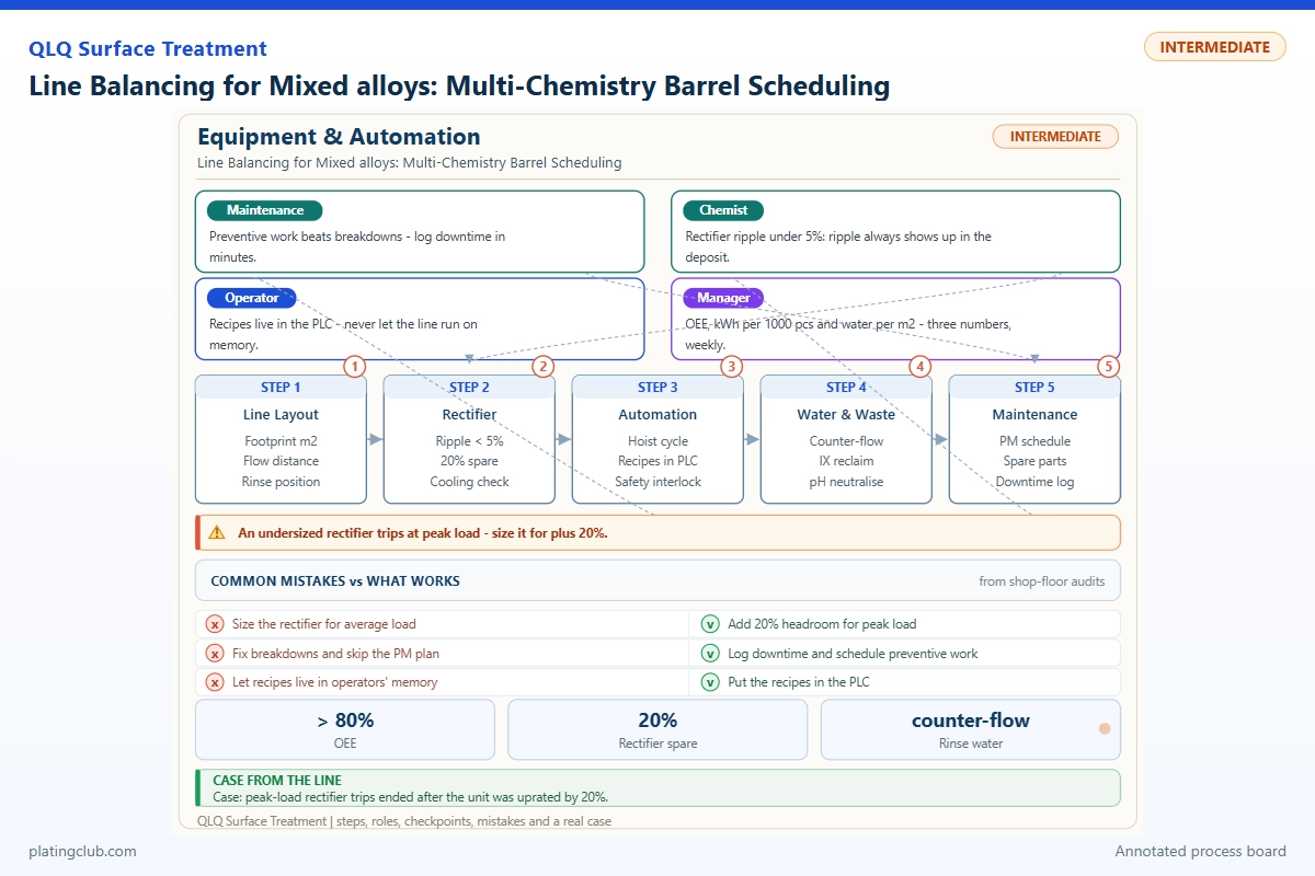
Line Balancing for Mixed alloys: Multi-Chemistry Barrel Scheduling
A mixed-alloy order book does not mean mixed alloys belong in one barrel. Zinc-alloy bag fittings, brass components and steel fasteners can require different cleaning, activation, strike and finishing routes. Scheduling succeeds when every batch reaches its next bath within its approved transfer window, without carrying incompatible solution into another process.
For junior technicians with established shop-floor experience, the priority is practical: identify the route, load consistently, keep electrical contact stable, and flag queues before activated parts wait too long. Do not change chemistry or increase current simply to recover a late order. Balance the schedule around the slowest approved operation, not the fastest hoist movement.
Evidence boundary: QLQ knowledge-base notes support barrel loading, rotation, solution circulation and bath-control principles. They do not contain measured trials for this scheduling topic. The examples below are explicitly planning exercises; calculated thickness is not a laboratory result. Experimental measurements remain to be confirmed by the plant.
1. Assign a route before assigning a start time
Use one traveler per batch. Write the substrate, part number, surface condition, coating stack, approved recipe revision, barrel identity, estimated surface area and inspection requirements. Equal weights of two different fittings do not necessarily present equal surface areas or tumble equally. Keep different alloy families separate unless an engineer has qualified the combined load.
| Batch family | Route decision | Scheduling consequence | Release check |
|---|---|---|---|
| Zinc-alloy cast fittings | Use the qualified zinc-alloy cleaning and barrier/strike sequence before the specified finish. | Reserve the strike and following bath together; avoid an unplanned activated queue. | Confirm barrier coverage and adhesion on representative parts. |
| Brass fittings | Use the approved brass activation and coating stack. | Do not borrow the zinc-alloy activation recipe to simplify the board. | Check surface cleanliness and agreed appearance. |
| Steel fasteners | Follow the drawing and approved steel route; high-strength material needs additional engineering review. | Include any required embrittlement-control treatment and deadline in the schedule. | Verify material identity and required post-treatment records. |
These are routing principles, not complete pretreatment recipes. Exact strike chemistry and activation times are process-specific and require confirmation. Never put bare zinc-alloy parts directly into an acid nickel bath merely because the nickel tank is available.
2. Calculate the bottleneck and protect it
For a station with identical available positions, estimate capacity as positions × 60 / occupied minutes, in batches per hour. Occupied time includes immersion, draining and any loading time that actually blocks that station. Separate offline loading from tank occupancy so the same minutes are not counted twice.
Worked scheduling scenario A: Suppose a qualified nickel operation occupies one position for 45 minutes and two positions are available. Its nominal capacity is 2.67 batches/hour, so a shared upstream release should be no faster than one batch every 22.5 minutes. If the strike occupies one position for 12 minutes, its nominal capacity is five batches/hour. Releasing from the strike at that rate would create a nickel queue.
Worked scheduling scenario B: Suppose two brass batches occupy nickel for 30 minutes each and one zinc-alloy batch for 45 minutes. They require 105 position-minutes. With two positions, the workload lower bound is 52.5 minutes; however, without splitting batches, the best simple allocation takes 60 minutes: two brass batches on one position and the zinc-alloy batch on the other. Hoist conflicts and transfers can extend this further.
Both scenarios use assumed times, not customer production records. Place the longest qualified batch first, stagger compatible batches, and reserve shared rinses and transfers. Keep waiting work before activation whenever possible. If a downstream station fails, stop releasing upstream batches rather than parking activated parts in air.
3. Working formulation: an unbrightened Watts nickel reference
The Nickel Institute Nickel Plating Handbook, Table 2 gives the following established base-electrolyte ranges. Typical values here are selected mid-range reference targets, not a QLQ proprietary recipe. This table is complete for the three-component unbrightened base bath; decorative bright nickel additionally requires a qualified supplier additive package.
| Component | Range | Typical | Function | Replenishment |
|---|---|---|---|---|
| Nickel sulfate, NiSO4·6H2O | 240–300 g/L | 270 g/L | Main nickel-ion source. | Analyze nickel and account for anode supply; add an approved calculated quantity only after authorization. |
| Nickel chloride, NiCl2·6H2O | 30–90 g/L | 60 g/L | Supports conductivity and nickel-anode dissolution. | Analyze chloride separately; do not infer chloride demand from nickel alone. |
| Boric acid, H3BO3 | 30–45 g/L | 40 g/L | Helps control cathode-interface pH. | Analyze, calculate the deficit, and replenish using the approved dissolution procedure. |
| Deionized water | To final working volume | 1 L final solution | Solvent; establishes concentration basis. | Restore the marked working level before interpreting concentration results. |
Do not substitute anhydrous salts gram-for-gram. For example, a confirmed 5 g/L boric-acid deficit in a 1,000 L bath corresponds to 5 kg pure material before purity correction. Mixing, dissolution and repeat analysis still require the approved procedure. pH adjusters are controlled additions, not fixed recipe ingredients.
The handbook's general Watts operating envelope includes 40–60°C and pH 3.5–4.5. Barrel current settings must be separately qualified: intermittent contact, load geometry and barrel resistance mean a rack-plating current-density range cannot automatically become a barrel production setting.
4. Trend normal variation against stop-and-review limits
The narrower bands below are proposed commissioning control limits, not universal defect thresholds. An engineer must approve them against the actual bath, equipment and product. Where a site limit is tighter, it takes precedence. Record trends rather than correcting every small reading fluctuation.
| Parameter | Normal working band | Danger / review threshold | Junior technician action |
|---|---|---|---|
| Bulk pH | 3.8–4.2 | Below 3.5 or above 4.5 | Hold new loads, verify the calibrated reading and notify bath control. |
| Temperature | 50–55°C | Below 40 or above 60°C | Check the independent sensor and heating/cooling status. |
| Nickel sulfate hexahydrate equivalent | 260–280 g/L | Below 240 or above 300 g/L | Request analysis; check working volume before additions. |
| Nickel chloride hexahydrate equivalent | 50–70 g/L | Below 30 or above 90 g/L | Check chloride analysis and anode condition. |
| Boric acid | 35–42 g/L | Below 30 or above 45 g/L | Escalate; inspect for undissolved material. |
| Batch surface area | Within ±5% of the qualified load | More than ±10% deviation | Recheck count and area estimate; obtain a revised current instruction. |
| Barrel rotation | Within ±10% of qualified speed | Stall or more than ±20% deviation | Stop under the fault procedure; isolate before mechanical inspection. |
A warning does not prove a particular defect. Examine appearance, thickness distribution, contact condition and chemistry together. Repeated small drifts in one direction deserve review even before a stop limit is reached. Never diagnose contamination from pH alone.
5. Validate the schedule with a controlled batch trial
Compare the existing release sequence with a staggered sequence using matched parts and the same coating stack. Keep bath composition, approved load, rotation and current program unchanged. Run at least three paired batches per alloy family. Sample representative production parts; a fixed coupon may not reproduce intermittent barrel contact.
For nickel, Faraday's law gives a planning estimate: thickness (µm) ≈ 12.3 × effective current density (A/dm²) × time (hours) × efficiency. The coefficient follows from nickel's molar mass, divalent deposition and density. The illustrative 95% efficiency is an assumption, not measured barrel performance.
| Trial / batch | Test condition | Calculated mean nickel thickness | Measured minimum / maximum | Adhesion / corrosion result |
|---|---|---|---|---|
| A: baseline release | Matched qualified parts; 1.0 A/dm² effective average; 45 min; assumed 95% efficiency | 8.8 µm | Pending XRF or cross-section measurement | Pending agreed test |
| B: staggered release | Same alloy, coating stack, load and bath; same 1.0 A/dm², 45 min and assumed efficiency; only release timing changes | 8.8 µm | Pending identical sampling | Pending identical test |
| C: reduced-time calculation only | Same assumed current and efficiency; 35 min; not authorized for production | 6.8 µm | Not measured | No performance claim |
Rows A and B should deliver comparable quality while B reduces waiting. Record queue time, completed acceptable batches and rework separately. Row C shows why shortening dwell to repair a queue can sacrifice thickness. Calculated mean thickness cannot demonstrate the minimum coating on recessed surfaces.
For corrosion testing, record the specified method, exposure duration, complete coating stack, conditioning, inspection interval and failure criterion. Compare like substrates only. Do not invent salt-spray hours or hardness values, and do not equate a nickel-thickness calculation with corrosion resistance. No measured salt-spray or hardness dataset was available for this article.
6. Engineer Notes: seven actions that protect throughput
- Label the barrel and traveler together. Verify alloy, recipe revision and destination tank before each immersion; quarantine unidentified loads.
- Weigh and count before activation. Compare the load with its qualified surface-area and fill limits, not just the nominal kilogram capacity.
- Inspect danglers and contacts. Check wear and cleanliness under the approved isolation procedure; unstable contact can mimic a chemistry problem.
- Reserve the next station. Confirm the downstream slot before releasing a batch into activation or strike; use the approved maximum transfer time.
- Keep drain time consistent. Follow the validated drain and rinse sequence; never extend draining so long that sensitive surfaces dry.
- Separate incompatible chemistry circuits. Use assigned barrels, transfer tools and rinses where required. Never allow acid into cyanide-bearing equipment or waste streams.
- Escalate a missed slot immediately. Record actual waiting time and obtain an approved recovery route; do not improvise reactivation or extra plating time.
Follow site SDS, ventilation and PPE requirements. Waste routing belongs on the process map, not only in the environmental office. When changing chemistry families, an empty barrel is not necessarily a clean barrel: retained solution in holes, seams and contact assemblies must be addressed by the validated cleaning procedure.
7. Shift Checks: make the handover reproducible
| Shift stage | Check item | Frequency | Acceptance standard | Record |
|---|---|---|---|---|
| Before shift | Batch identity, route and downstream reservations | Every planned batch | Traveler complete; qualified recipe and reserved slot present | Dispatch board and traveler initials |
| Before shift | Bath release, pH, temperature and working level | Before first load | Approved limits met; analysis release current | Bath log with time and instrument identity |
| Before shift | Barrel, contacts, rotation and safety devices | Each barrel at startup | No damage; qualified speed; safety checks passed | Equipment checklist |
| During shift | Load weight, estimated area and current program | Every batch | Matches approved recipe and load envelope | Batch weight, count and ampere-hours |
| During shift | pH trend, temperature and abnormal current | Temperature/current continuously; pH per approved plan | No unresolved alarm; trends inside site limits | Trend log and corrective-action reference |
| During shift | Transfers, rinse condition and appearance | Every transfer; rinse measurement per control plan | Qualified transfer window and rinse limit met | Actual entry/exit times and inspection result |
| After shift | Quality release and remaining work | Every completed or held batch | Inspection signed; holds clearly segregated | Quality report and hold location |
| After shift | Additions, faults and next-shift capacity | At handover | Authorized additions traceable; unavailable stations marked | Signed handover with next required action |
A useful handover says what changed, which batches are affected, and who owns the next action. “Nickel running slowly” is insufficient. Include tank identity, alarm time, current trace, affected travelers and the authorized restart condition.
8. Technician questions to ask an AI assistant
“Can I put zinc-alloy sliders and brass fittings in the same barrel to finish the order faster?”
Not without a specifically qualified mixed-load process. Different activation needs, geometry and coating stacks can prevent consistent coverage. Ask the engineer whether an approved combined traveler exists; otherwise keep loads separate and improve release timing. An AI answer cannot authorize a route change.
“The nickel tank has a queue. Can I increase amps and reduce plating time?”
Do not change the approved current program. Higher nominal current may increase local burning or hydrogen evolution without fixing intermittent contact. First verify capacity, load area, contacts and shared-transfer conflicts. Use an engineer-approved trial to establish whether any shorter cycle still meets minimum thickness and appearance requirements.
“My batch waited after activation. Should I rinse it again and continue?”
Check the actual wait against the approved transfer window. If exceeded, hold the batch and request the documented recovery instruction. Another rinse does not necessarily remove oxide or restore adhesion. Record alloy, bath, delay, surface condition and traveler number so the engineer can decide on reactivation or rework.
9. What Would You Like to Solve?
Send your alloy list, coating stacks, station counts, occupied cycle times, barrel loads, queue log and current quality criteria to [email protected]. These details allow a scheduling review to distinguish a genuine capacity shortage from avoidable release conflicts. For the equipment-and-chemistry context, see turnkey surface-treatment lines, equipment, chemicals and support.
Source notes: QLQ internal knowledge-base entries “Rack and Barrel Plating” and “Plating Brighteners and Additives,” under the Surface Treatment Process folder, support the loading and monitoring guidance. Published Watts ranges are attributed above to the Nickel Institute. Schedule values, proposed control bands and calculated trial thicknesses are transparent engineering examples, not verified QLQ production results.