
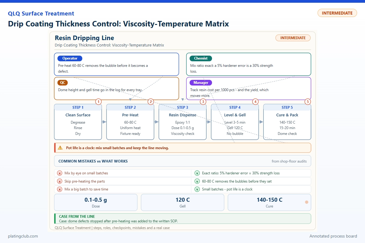
Drip Coating Thickness Control: Viscosity-Temperature Matrix
For intermediate resin-dripping technicians, thickness control means separating three problems: how much resin reaches the part, how that resin spreads, and when curing arrests the shape. A warmer mixture may dispense faster but also escape the recess sooner. An older mixture may retain a taller dome while leaving corners uncovered. Turning up pressure alone can hide either problem until rejects appear downstream.
This guide addresses two-component epoxy doming on plated zinc-alloy bag hardware, recessed pullers, and decorative badges. It does not describe dip coating, silicone moulding, PVC dispensing, or an aqueous plating bath. There is no meaningful bath-pH adjustment here. Establish a product-specific operating window rather than borrowing limits from another finishing process.
1. Define thickness before adjusting the machine
A dome has an average thickness, a centre height, and an edge profile; these are not interchangeable acceptance criteria. Agree with quality which measurements matter. For a recessed decoration, record minimum corner coverage and overflow as well as centre height. Measure a cured cross-section or a validated optical profile at fixed locations. A magnetic coating gauge cannot automatically isolate epoxy above a multilayer metal finish.
Use gravimetric dispensing to separate delivery from spreading. Collect ten shots in a tared container, weigh the total, and repeat three times. Confirm the balance can resolve a single-shot change smaller than the permitted tolerance. Also weigh individual shots when intermittent bubbles or valve leakage are suspected; an average can conceal alternating heavy and light deposits.
Working formula: average wet thickness h = m / (rho × A). With m in grams, density rho in g/cm³, and coated area A in cm², h is in centimetres. Illustrative calculation: 0.055 g / (1.10 g/cm³ × 1.00 cm²) = 0.050 cm, or 0.50 mm. Density and area are assumed here, not certified material properties. This estimate excludes curing shrinkage, overflow, and the nonuniform dome profile.
At constant retained mass and area, changing viscosity redistributes the resin rather than creating more material. However, on a pressure-time dispenser, viscosity also changes shot mass. Measure both variables before deciding whether the corrective action belongs at the thermal conditioner, dispensing valve, fixture, or cure station.
2. Working formulation: complete two-component charge
Use a purchased, qualified resin/hardener pair. The table gives a complete solvent-free production charge, not a reverse-engineered raw-material synthesis recipe. The reference pair is E-1155/H-1155, whose manufacturer publishes separate 3:1 and 4:1 weight-ratio options. Select one qualified option and lock it; do not treat the interval between them as an adjustable production range.
| Component | Range | Typical | Function | Replenishment |
|---|---|---|---|---|
| Matched epoxy Part A | 100 parts by weight; fixed basis | 45.00 g | Resin phase for the clear dome | Refill the separate A reservoir with the same approved grade and traceable lot. |
| Matched hardener Part B | 33.33 parts per 100 A for selected 3:1 route; 25 parts only for separately approved 4:1 route | 15.00 g for selected route | Curing component; controls network properties with A | Refill B separately; recalibrate delivery ratio after reservoir or lot changes. |
| Solvent, pigment, filler, and field-added additives | 0 for this clear reference charge | 0.00 g | Excluded to keep the qualified system unchanged | No replenishment; coloured systems require a separately approved formulation. |
| Total mixed charge | 60 g reference batch | 60.00 g | Defined batch basis for working-time comparison | No topping up mixed material; discard at the validated age limit. |
The selected composition is 75% A and 25% B by total weight. A weight ratio is not a volume ratio. Do not add hardener to accelerate production or thinner to rescue an ageing batch. If purchasing supplies a different pair, replace this entire formulation basis with its current technical data sheet.
Manufacturer reference values and mixing options are available in the E-1155/H-1155 technical property table. Supplier data are a starting point for qualification, not evidence of adhesion or corrosion performance on your plated hardware.
3. Build the viscosity-temperature matrix
Measure mixed viscosity using a documented spindle, speed, sample volume, conditioning time, and elapsed time after mixing. Keep the method inside the instrument's valid torque range. Do not compare a Part A certificate with a mixed-resin reading. In a reactive system, temperature and batch age interact: initial warming lowers flow resistance, while faster reaction subsequently raises it.
The following matrix is a commissioning worksheet, not measured material data. The three temperatures are trial setpoints. Run at least three independently mixed batches at each point, using identical substrate preparation, shot geometry, and approved curing conditions. Condition the unmixed components first; avoid repeatedly heating an ageing mixed cup.
| Trial temperature | Fresh mix: 5 minutes | Mid-age: 15 minutes | Late trial: 25 minutes | Thickness-control decision |
|---|---|---|---|---|
| 20°C | Measure viscosity and shot mass | Repeat; inspect corner filling | Repeat only if still usable | If mass falls, distinguish viscosity increase from nozzle obstruction. |
| 25°C | Establish reference viscosity eta-ref | Calculate eta/eta-ref | Inspect levelling and bubbles | Set the qualified baseline from cured profiles, not appearance alone. |
| 30°C | Check excess spreading and mass | Track cup-temperature rise | Stop at validated working limit | Reject a condition that produces overflow or an unstable working window. |
Plot viscosity and retained shot mass against elapsed time separately. A useful recipe specifies temperature, maximum mixed age, shot mass, and accepted profile together. If the same mass produces different centre heights, investigate wetting, substrate temperature, fixture tilt, and recess dimensions before changing the dispensing pulse.
4. Reference experimental comparison and local coupon plan
No QLQ coupon or customer batch dataset was available for this article. The numerical comparison below reproduces supplier-published test properties for two weight ratios of the reference pair. Specimen geometry, sample count, and test standards are not disclosed on that page; this is not a certified test report or a local validation result.
| Comparison specimen / formulation | Hardness | Water absorption | Film thickness / salt spray | Test condition |
|---|---|---|---|---|
| Supplier reference, A:B = 3:1 by weight | Shore A 75–85 | 0.12% | Not reported | Water absorption: 25°C, 24 hours; hardness cure/specimen method not stated. |
| Supplier reference, A:B = 4:1 by weight | Shore A 45–55 | 0.18% | Not reported | Water absorption: 25°C, 24 hours; hardness cure/specimen method not stated. |
For local qualification, assign coupons to each temperature-and-age cell. Record resin lot, plated substrate lot, retained mass, centre/edge thickness, visible bubbles, adhesion, and cured witness hardness. Use suitably thick witness specimens for Shore testing; a thin dome over rigid metal can distort the result. Retain an uncoated plated control to distinguish coating effects from upstream plating variation.
If corrosion resistance is required, agree the exposure method, duration, scribe condition, edge masking, and failure definition with the customer before testing. Do not infer salt-spray hours from hardness or water absorption. Leave unavailable results explicitly pending rather than converting an attractive dome into a durability claim.
5. Normal bands versus action thresholds
These are proposed commissioning controls, not universal chemistry limits. Replace them with validated capability limits and the supplier's restrictions. A danger threshold means stop dispensing and quarantine material since the last accepted check; it does not prove a specific failure mechanism.
| Parameter | Provisional normal band | Danger / stop threshold | Likely consequence and response |
|---|---|---|---|
| Conditioned resin temperature | 25 ± 1°C | Below 22°C or above 28°C | Delivery and spreading change; recondition unmixed components and repeat shots. |
| Mixed viscosity, same method and age | 0.90–1.10 × qualified eta-ref | Below 0.80 or above 1.20 × eta-ref | Overflow or poor levelling; check temperature, ratio, and batch age. |
| A:B weight ratio | 3.00:1 target; proposed ±1% relative tolerance | Deviation greater than ±2% | Unqualified cure properties; reject mix and investigate metering. |
| Individual shot mass | Qualified target ±3% | Any shot outside ±5% | Average thickness changes; inspect valve, bubbles, pressure, and nozzle. |
| Mixed-material age | 0–20 minutes for initial trials | Over 25 minutes, or earlier viscosity failure | Age-related inconsistency; replace mix, never blend with fresh material. |
| Part temperature above dew point | At least 5°C margin | Below 3°C margin or visible condensation | Contaminated interface; stop and dry/recondition parts by approved procedure. |
| Fixture tilt | Within ±0.2° from approved level | Beyond ±0.5° | Asymmetric profiles; clean and re-level fixture before restart. |
Trend values, not just pass/fail boxes. Three successive readings drifting toward a boundary deserve investigation before a stop threshold is crossed. Temperature and viscosity should be logged beside shot mass so the next technician can see whether compensation has accumulated.
6. Two practical troubleshooting scenarios
Scenario A: heavy morning shots on recessed pullers. This is a diagnostic example, not a documented customer case. The pressure setting matches yesterday, but components were stored cold. Verify actual resin temperature, then weigh shots before adjusting pressure. Recondition sealed, unmixed containers, recalibrate delivery at the approved temperature, and compare cured corner coverage. Release only after consecutive accepted checks; do not assume a corrected average removes early-batch defects.
Scenario B: acceptable mass but uneven badge domes. Another diagnostic example: one side has a tall meniscus while the opposite corner is bare. Keep shot mass unchanged initially. Check fixture level, recess cleanliness, part temperature, and whether the defect follows a particular cavity. Dispense a reference coupon beside the suspect part. If the coupon levels correctly, investigate geometry or surface contamination; if both fail as mixed age increases, shorten the working window and repeat the matrix.
7. Engineer Notes
- Label every mixed cup with A/B lot numbers, weighed quantities, mixing time, and discard time; start the clock when components first contact.
- Scrape the mixing vessel walls and bottom using the approved method; avoid whipping air into the blend. Validate any vacuum step against the supplier's instructions.
- Check resin temperature with a verified probe, not the heater display. Record probe location because reservoir and nozzle temperatures may differ.
- Perform separate A and B metering checks after maintenance; total mixed output alone cannot reveal ratio error.
- Keep levelling fixtures stationary until the validated handling point. Log actual part temperature during cure rather than relying only on oven air.
- Quarantine product made after the last good check when a limit fails. Identify affected batches before restarting with a fresh mix.
- Review the product safety data sheets before handling. Use specified gloves, eye protection, and ventilation; never use an open flame to remove bubbles.
8. Shift Checks
| Shift stage | Check item | Frequency | Acceptance standard | Record |
|---|---|---|---|---|
| Before shift | Material identity, ratio, balance, fixture level | Each startup and recipe change | Approved lots and recipe; checks within qualified limits | Startup sheet, calibration ID, operator |
| Before shift | Temperature and trial shots | Before first production part | Temperature band met; three accepted ten-shot groups | Probe readings and shot weights |
| During shift | Mixed age, viscosity, shot mass, profile | Every batch; mass/profile every 30 minutes initially | All validated bands met; no overflow or uncovered corners | Batch log and retained coupon ID |
| During shift | Reservoir refill and nozzle intervention | After every intervention | Ratio and delivery rechecked before release | Intervention reason and restart results |
| After shift | Cure records, rejects, remaining mix | Each shift end | Traceable cure; expired mix segregated; holds identified | Handover sheet and disposition log |
9. Technician-to-AI FAQ
These are example technician prompts, not quotations from recorded customer conversations.
“AI, the resin is thicker this morning. Can I just increase dispensing pressure?”
First compare actual temperature, mixed age, and viscosity with the qualified reference. Weigh the shots. Pressure compensation may restore mass while leaving poor corner filling. Recondition unmixed components or replace aged mix, then validate the cured profile before production.
“AI, my shot weight is correct, but the centre thickness keeps changing. What should I check?”
Verify retained mass rather than delivered mass, then inspect overflow, coated area, fixture level, surface cleanliness, and part temperature. Compare fixed profile locations after the same cure. A dome can redistribute identical mass into a different centre height.
“AI, can I add more hardener to shorten curing without changing the thickness?”
No field adjustment is justified. Ratio changes can alter cured properties even if the dome looks unchanged. Use a supplier-approved faster system or qualified cure schedule, then repeat delivery, profile, adhesion, and durability qualification.
What Would You Like to Solve?
Send the substrate and plating stack, resin data sheet, ratio, temperature/age log, shot weights, and centre/edge measurements to [email protected]. Describe the failure location and when it appears. For upstream and downstream coordination, review surface-treatment line equipment, chemicals, and process support.
Knowledge-base scope check: 03-Equipment Technology / Company Directory / Machine Directory / Page 25 distinguishes silicone and PVC dispensing equipment; it provides no epoxy thickness matrix. Epoxy compatibility and the provisional controls above require confirmation for the actual materials and hardware.