

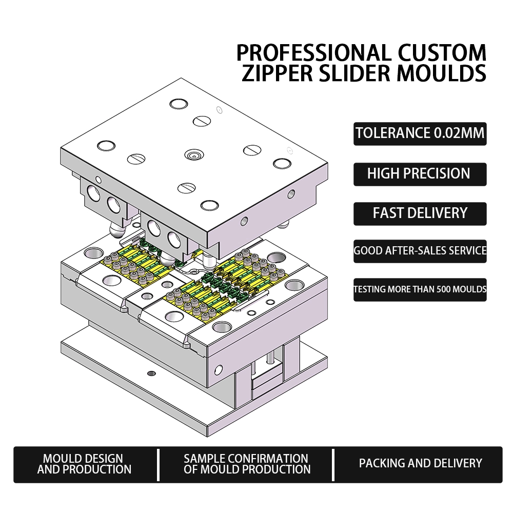
Flash on a slider mould grew from 0.02 mm to 0.15 mm over three weeks, and nobody measured it until parts started catching in the die. The parting line had worn at the core pin area, and clamp tonnage had never been verified.
This intermediate case guide covers flash measurement, parting line wear checks, clamp tonnage and the inspection schedule that catches wear early.

Common Mistakes and How to Avoid Them
| Mistake | Why It Happens | Practical Fix |
|---|---|---|
| 1. Flash never measured | Wear grows unseen | Feeler gauge weekly |
| 2. Wear blamed on steel only | Clamp and alignment missed | Check tonnage and die set |
| 3. Tonnage set by habit | Low clamp grows flash | Calculate per projected area |
| 4. Vents eroded | Flash appears at vents first | Inspect vent depth 0.05-0.15 mm |
| 5. Spotting skipped | Poor contact hides wear | Spot after every service |
| 6. Dowels and bushes worn | Misalignment opens the line | Check die set alignment monthly |
| 7. Flash tolerated | Catching parts stop the line | Act at 0.10-0.15 mm |
| 8. Service by failure | Wear becomes damage | Service by shot count |
| 9. No flash log | Trend invisible | Log flash per mould weekly |
Best Practices
- Measure parting line flash weekly with a feeler gauge
- Verify clamp tonnage against the die calculation
- Spot the parting surfaces after every service
- Inspect vent depth and erosion per set-up
- Check die set alignment monthly
- Log flash per mould to see the trend
Implementation Roadmap
| Step | Frequency |
|---|---|
| Measure flash | Weekly per mould |
| Verify tonnage | Per set-up and machine move |
| Spot parting line | After every service |
| Check alignment | Monthly |
| Service by shot count | Per mould schedule |
Flash control flow
- Measure - Feeler gauge weekly. (Unmeasured flash grows for weeks.)
- Verify - Tonnage and alignment. (Low clamp opens the line.)
- Service - Spot and refit by shot count. (Failure-based service damages steel.)
- Log - Flash per mould weekly. (No log, no trend, no early catch.)
Flash is a symptom of clearance, tonnage and alignment. | A weekly feeler gauge beats a monthly surprise.
Parting line data
Reference values for mould flash control.
| Parameter | Reference | Why It Matters |
|---|---|---|
| Parting line target | Under 0.05 mm | New or refitted moulds hold this |
| Flash action level | 0.10-0.15 mm | Service before parts catch |
| Clamp tonnage | Projected area x 500-700 bar (zinc) | Per die, not per habit |
| Vent depth | 0.05-0.15 mm | Eroded vents flash first |
| Spotting coverage | 80% ink contact or more | Poor contact means wear or misalignment |
| Alignment check | Monthly, dowel and bush | Wear opens the parting line |
| Service trigger | Per shot count, e.g. 50k-100k | Preventive, not reactive |
Flash growth log
| Week | Flash mm | Action |
|---|---|---|
| Week 1 | 0.02 | Monitor |
| Week 2 | 0.06 | Monitor |
| Week 3 | 0.15 | Service, check tonnage |
| After refit | Under 0.05 | Resume log |
Case 1 - flash caught at 0.15 mm before a stoppage
Scenario. Flash on a zinc slider mould grew from 0.02 mm to 0.15 mm over three weeks. Parts began catching in the die and the line stopped twice; the parting line had worn at the core pin area.
Action.
Result.
Case 2 - flash appeared after a machine move
Scenario. A bag frame mould produced clean parts for a year, then flashed within days of being moved to a smaller machine with less clamp force.
Action.
Result.
Frequently Asked Questions
How do I measure flash?
A feeler gauge at the parting line, weekly, at the same points each time.
What flash is acceptable?
Under 0.05 mm on a healthy mould; act at 0.10-0.15 mm before parts catch.
Why did flash grow slowly?
Wear is gradual; without measurement it is invisible until parts catch.
Is flash always wear?
No - low clamp tonnage and die set misalignment open the line too.
How do I check tonnage?
Calculate from projected area and cavity pressure, then verify on the machine display.
What is spotting?
Inking the parting surfaces and closing to check contact; aim for 80 percent or more.
How deep should vents be?
0.05-0.15 mm; deeper vents flash, blocked vents trap gas.
When should I service the mould?
By shot count, about every 50k-100k shots for this part class, not after failure.
Why log flash weekly?
The trend shows wear rate; a jump from 0.06 to 0.15 in one week means tonnage or alignment.
What Would You Like to Solve?
Tell us your flash pattern, machine tonnage and service history, and we can work through the measurement and tonnage checks for your moulds.