
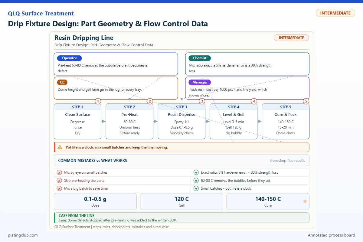
Drip Fixture Design: Part Geometry & Flow Control Data
A resin-dripping fixture is a flow-control tool, not simply a tray that holds parts. On plated zinc-alloy bag fittings, badges, and decorative pullers, a small seating error can turn an acceptable shot into an overflowing edge, a dry corner, or an uneven dome. Intermediate technicians should diagnose three interacting variables: the actual fill geometry, the position of that geometry during leveling, and the changing flow behavior of mixed resin.
This guide addresses two-component epoxy doming on recessed or bounded decorative surfaces. It does not describe PVC plastisol molding, silicone dispensing, or an electroplating bath. Epoxy has no useful production pH setpoint here. Begin with a qualified resin system and substrate; then establish a fixture window through controlled trials.
Evidence boundary: Manufacturer reference properties are identified below. Dimensions, shot calculations, and control bands are engineering examples, not QLQ production results. Verified customer trial records and salt-spray results for this fixture application are unavailable and require confirmation. Do not substitute predicted thickness for measured coating thickness.
1. Define the fill surface before drawing the nest
Measure the resin boundary rather than the external silhouette. A puller can have a flat-looking face while its decorative recess slopes around a raised logo. Record projected fill area, recess depth, rim continuity, corner radius, holes, and nearby moving interfaces. An open chain eye is an escape path, not extra fill area.
Use three stable underside locating pads where practical, with separate lateral stops and a light retaining feature. Place supports beneath stiff regions. Avoid clamping thin arms or decorative edges: springback after release can change the dome orientation. Provide relief around casting flash so an occasional burr does not lift the whole part.
| Geometry feature | Fixture response | Verification |
|---|---|---|
| Flat recessed badge | Support the underside; preserve nozzle access to the entire recess. | Measure the fill-plane angle with a seated reference part. |
| Curved puller with raised lettering | Orient the intended fill region, not the outer back face. | Section sacrificial parts at the logo and perimeter. |
| Open hole beside the recess | Keep the dispensing route away from the opening; trial a removable barrier if necessary. | Check barrier removal for resin tearing and residue. |
| Thin decorative arms | Use low-force retention and locally supported loading. | Compare loaded and released geometry. |
Give every pocket an identifier and keep supports inspectable. Separate clean contact surfaces from spill-catching features. Release sprays can contaminate the coating boundary; qualify contact materials and cleaning methods instead of assuming a low-adhesion plastic is automatically compatible.
2. Working Data & Formula Notes
A complete usable shop-floor formulation can be a purchased, matched two-part system. Its undisclosed internal chemistry must not be reconstructed from a generic recipe. The example below uses Fong Yong E-1158-2/H-1158-2, whose manufacturer specifies a 3:1 mass ratio. This is a reference material, not a QLQ formulation or an endorsement for plated zinc alloy; adhesion must be qualified separately. Manufacturer processing and property reference.
| Component | Range | Typical | Function | Replenishment |
|---|---|---|---|---|
| E-1158-2, matched Part A | Fixed at 100 mass parts; no discretionary adjustment | 45.00 g in a 60.00 g batch | Supplied epoxy resin formulation | Weigh fresh material into a new clean vessel; retain lot identification. |
| H-1158-2, matched Part B | Fixed at 33.333 mass parts per 100 parts A | 15.00 g in a 60.00 g batch | Matched curing formulation | Replenish unmixed supply only; never top up an aging mixed cup. |
| Additional solvent, pigment, filler, accelerator, or defoamer | 0 in this complete clear formulation | 0 g | Excluded to preserve the supplier-defined system | No addition without written compatibility instructions and requalification. |
The range column deliberately locks the chemical ratio. It is not a tuning window. Faster cure must not be obtained by adding hardener. Follow the current supplier instructions for mixing and safe handling; wear SDS-specified protection, prevent skin contact, and manage ventilation and waste through the site's chemical-control procedure.
Geometry calculation: V = A × h / 1000, where V is milliliters, A is square millimeters, and h is average fill thickness in millimeters. For A = 240 mm² and h = 0.80 mm, V = 0.192 mL. This excludes a raised dome, lettering displacement, shrinkage, and retained material in the nozzle. Establish the final shot experimentally.
Mass conversion: m = density × V. If measured mixed density is 1.10 g/mL, the calculated mass is 0.211 g. That density is an assumption for the worked example, not a published value for this resin. Use a calibrated balance and determine actual density before converting production shots.
3. Control level, nozzle position, and residence time
A tilted fill plane produces a gravity-driven height difference. Across a 20 mm feature, height difference = length × tan(angle). At 0.2°, the difference is approximately 0.070 mm; at 0.5°, approximately 0.175 mm. Against a nominal 0.80 mm fill, the latter is a significant geometric disturbance before meniscus effects enter the picture.
Check the fixture both on the dispensing bench and on its curing shelf. A perfectly level bench does not compensate for a warped tray. Repeat measurements with loaded parts, because locating pads can accumulate cured resin and parts can vary in underside geometry.
Start a shot inside the bounded region. For a long recess, trial a central bead or several controlled deposits rather than a large impact near the rim. Nozzle stand-off, travel speed, stop delay, and suck-back interact; weigh completed shots after any nozzle replacement. Component viscosity is not mixed viscosity, and supplier pot life is not a guarantee of unchanged flow until the final minute.
4. Normal variation versus stop-and-investigate thresholds
These are proposed commissioning limits for the worked geometry, not universal material specifications. Validate them against spill onset, corner coverage, and measurement uncertainty. Values between the normal band and stop threshold require investigation and increased sampling. The signed process sheet takes precedence.
| Parameter | Proposed normal band | Danger / hold threshold | Action |
|---|---|---|---|
| Loaded fill-plane tilt | 0–0.2° | >0.5° | Stop; inspect supports and relevel the loaded tray. |
| Individual shot mass | Qualified target ±3% | Deviation >5% | Hold output since the last passing sample; check nozzle and flow. |
| Part B mass relative to Part A | 33.333 parts; proposed weighing control ±1% relative | Outside that weighing control | Quarantine the mix; this is not permission to change stoichiometry. |
| Material conditioning temperature | 24–26°C for the initial trial | <22°C or >28°C | Recondition and recheck flow; do not compensate with solvent. |
| Mixed-material age | 0–15 minutes in initial trials | >20 minutes pending validation | Replace the mix; investigate earlier if shots already drift. |
| Flow-test spread diameter | Qualified fresh-mix baseline ±10% | Deviation >20% | Check temperature, timing, ratio, and contamination. |
| Nozzle stand-off | Provisional 1.0–2.0 mm | Contact or >3.0 mm | Reset height and inspect for splashing or stringing. |
For the flow test, deposit a fixed mass onto the same clean reference surface, at the same temperature, and measure spread after the same elapsed time. Its result is a comparative process indicator, not a viscosity measurement. Trend it alongside shot mass rather than interpreting either number alone.
5. Experimental comparison and release evidence
The manufacturer's published reference data provide a material baseline: working life is 30–40 minutes for a 60 g mix at 25°C; reported cured hardness is Shore A 80–90, with room-temperature full cure at seven days or a stated heat-cure route. Those are supplier reference values, not measurements on plated fittings. Reference test conditions and limitations.
Use the following paired-coupon experiment to generate the missing fixture evidence. Run at least ten parts per condition, keeping substrate lot, preparation, resin lot, and nozzle unchanged. Record individual results, not only averages. Alternate tray positions to reduce position bias.
| Trial / material reference | Test condition | Thickness / geometry data | Hardness / durability data | Evidence status |
|---|---|---|---|---|
| Published E-1158-2/H-1158-2 baseline | 3:1 mass mix; pot-life test: 60 g, 25°C; room-temperature full cure: seven days | No metal-part film thickness reported | Supplier hardness: Shore A 80–90 at 25°C; no salt-spray result provided | Manufacturer reference, not an in-house batch |
| Coupon A: level fixture | 240 mm² recess; calculated 0.192 mL; 0.2° tilt; same approved cure | Calculated mean: 0.80 mm; geometric height difference: 0.070 mm | Measured thickness, adhesion, and hardness: pending | Calculated setup; test results require measurement |
| Coupon B: tilted fixture | Same recess and shot; 0.5° tilt; otherwise identical to A | Calculated mean: 0.80 mm; geometric height difference: 0.175 mm | Overflow count and edge thickness: pending | Controlled comparison, not a claimed result |
| Coupon C: late dispensing | Same setup as A; dispense at 20-minute mix age | Measure center and four edge locations after cure | Flow spread, bubbles, coverage, and witness hardness: pending | Residence-time challenge trial |
Section sacrificial parts to distinguish recess fill from dome height. Use a suitably prepared cured witness specimen for hardness; a thin dome over metal can bias a durometer reading. Any corrosion test must specify the complete plated stack, exposed edges, test method, duration, and acceptance criterion. Resin appearance alone cannot certify corrosion resistance.
6. Two practical diagnostic scenarios
Scenario A: rectangular badge overflows at one corner
This is a troubleshooting example, not a reported customer case. First inspect the corresponding pocket for cured deposits. Rotate the tray without changing the recipe and map where overflow occurs. If the defect follows the pocket, investigate seating; if it follows the workstation direction, investigate leveling. If random parts fail, measure recess capacity and incoming geometry. Do not reduce every shot to accommodate one defective nest: that can create dry corners elsewhere.
Scenario B: curved puller leaves a dry channel beside a logo
Keep mix age and shot mass constant while comparing deposit routes. A raised logo can divide the wetting front, so added volume may overflow the rim without reaching the channel. Trial smaller deposits on both sides, while maintaining the same total mass. If the dry region remains fixed, check surface contamination and the geometry itself. Validate adhesion on the actual plated finish before changing cleaners or adding surface treatments.
7. Engineer Notes
- Number every pocket and photograph the first qualified fill; preserve orientation in defect records.
- Check a loaded reference part at three tray positions after cleaning or maintenance.
- Weigh ten consecutive shots after nozzle replacement; retain the individual values and range.
- Start the mix-age timer when components first contact, not when dispensing begins.
- Follow the supplier's mixing procedure, including vessel-wall scraping; qualify degassing before introducing it.
- Transfer trays horizontally to verified curing supports; do not stack or tilt parts before the approved handling point.
- Quarantine suspect material and affected trays instead of blending old mix into fresh resin.
8. Shift Checks
| Shift stage | Check item | Frequency | Acceptance standard | Record |
|---|---|---|---|---|
| Before shift | Supports, retaining features, loaded level | Every tray; repeat after cleaning | Clean, undamaged, within signed tilt limit | Tray ID, measured angle, operator |
| Before shift | Balance and nozzle output | Startup and nozzle changes | Balance check passes; ten shots within approved window | Check weight, shot series, nozzle ID |
| During shift | Component weights and mix clock | Every mix | Correct matched components and approved mass-ratio control | Lot numbers, actual masses, start time |
| During shift | Coverage, overflow, flow spread | First tray per mix; provisionally every 15 minutes | Qualified appearance and flow band; no blocked openings | Pocket map, photos, flow value |
| After shift | Cure traceability and hold status | Every remaining tray | Approved cure completed or clearly marked in progress | Cure location, start/end times, disposition |
| After shift | Fixture cleaning and waste | Once, after safe unloading | No cured buildup; waste managed under site procedure | Cleaning sign-off and maintenance request |
9. Technician FAQ
“AI, my shot weight is stable, so why does one corner keep overflowing?”
Stable mass does not establish stable capacity or level. Compare pocket identity, loaded angle, actual recess dimensions, and rim damage. Swap a reference part between good and bad pockets. Change only one variable so the defect can be assigned to the part, fixture, or workstation.
“AI, can I add more hardener when the resin becomes slow to cure?”
No. Preserve the specified mass ratio. Check actual component temperature, weighing records, mixing completeness, cure conditions, and material identity. A wrong ratio can leave uncured regions. Hold suspect batches and use the current supplier instructions rather than a shop-floor correction by eye.
“AI, can I use our silicone dripping machine for epoxy on plated pullers?”
Do not assume compatibility. The QLQ catalog lists QLQ-LSMM, QLQ-LSVM, and QLQ-12LSDM for liquid silicone operations. Epoxy requires a separate review of wetted materials, metering, mixer design, cleaning, and cure requirements. Catalog naming alone does not establish suitability.
What Would You Like to Solve?
Send the fill-region drawing, plated finish, resin technical sheet, pocket photographs, shot-mass log, and defect map to [email protected]. Specify whether the problem is overflow, dry corners, bubbles, adhesion, or cure variability. For broader equipment and chemistry coordination, see turnkey surface-treatment lines, equipment, chemicals, and support. Fixture qualification should connect these records to an agreed release criterion, not an assumed universal recipe.
Knowledge-base source: QLQ Obsidian Vault, equipment catalog, page 25 (local note identifier: 03 / company catalog / machine catalog / page 25). It supports the silicone equipment names only; epoxy fixture trial outcomes remain unconfirmed. Additional material-family reference: Fong Yong doming resin overview, which distinguishes hard, flexible, and non-sag systems. Obtain current supplier documentation before production qualification.