
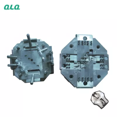
The gate and runner decide the fill pattern, and erosion changes it silently. Intermediate mould technicians own the geometry: measure, decide, restore.
This guide is the gate and runner tuning method for zinc die-casting moulds.
Common Mistakes and How to Avoid Them
The pitfalls that show up most often in real projects, with the cause and the practical fix.
| Mistake | Why It Happens | Practical Fix |
|---|---|---|
| 1. Gate sized by habit | Fill drifts | Measure against drawing |
| 2. Runner assumed balanced | Cavity starvation | Balance test |
| 3. Erosion ignored | Flow marks | Measure at threshold |
| 4. Polishing marks away | Cause remains | Measure first |
| 5. One cavity fixed only | Imbalance shifts | Balance the set |
| 6. No before measurement | Cannot judge | Record before work |
| 7. Wrong fill tuning | Mould not shot | Fix geometry first |
| 8. No first-article gate | Faults run | Gate after work |
Best Practices That Hold Up in Production
The operating disciplines that separate a reliable line from a reactive one.
- Measure the gate against the drawing
- Balance-test multi-cavity runners
- Refurbish at the threshold
- Record before and after
- Gate first articles
Implementation Roadmap
A practical sequence that can be adapted to your own project.
Process Flowchart
Gate and runner tuning flow
A step-by-step sequence with notes and cautions so every shift follows the same order.
- The gate is the fill fingerprint.
- Balance is the multi-cavity truth.
- Gate work is precision - qualified hands.
- Measuring tools need calibration.
Working Data & Formula Notes
Working data - gate and runner
Reference values for zinc die-casting moulds.
| Component / Parameter | Working Value / Role | What Changes Mean (annotation) |
|---|---|---|
| Gate thickness | 0.8-1.2 mm | Erosion changes fill velocity. |
| Runner diameter | 6-10 mm | Balances pressure to cavities. |
| Gate width | 2-4 mm | Feeds the fill pattern. |
| First article | Per cavity | Balance proof. |
Reference Data
Specifications and references cited in this guide. Confirm final parameters with your line supplier.
Tuning record
| Gate before | Gate after | Runner check |
| Cavity balance | Change made | First article |
| Signed | Date | Next check |
Implementation Cases
Case 1 - gate erosion that printed flow marks
Situation. Flow marks appeared on one face after a high shot count.
Approach. Gate measurement showed erosion below 0.8 mm; the gate was refurbished.
Outcome. Flow marks stopped.
Case 2 - a starving cavity in a multi-cavity mould
Situation. One cavity ran thin while others were fine.
Approach. A fill-balance test showed the runner starving that cavity; the runner was adjusted.
Outcome. All cavities filled evenly.
Frequently Asked Questions
Why measure the gate?
Erosion changes the fill pattern and prints flow marks.
What are the gate windows?
0.8-1.2 mm thick, 2-4 mm wide for zinc hardware.
How do I balance multi-cavity fill?
Compare first articles per cavity and adjust runners.
Why not polish flow marks away?
Polishing hides the cause; the erosion remains.
When do I refurbish?
At the measurement threshold before parts fail.
Why record before and after?
Evidence makes the decision repeatable.
Should I tune the shot instead?
Fix geometry first; the shot follows the mould.
What is the proof?
First articles per cavity after the work.
What Would You Like to Solve?
Measure the gate, balance the cavities, refurbish at the threshold and gate with first articles. The mould geometry decides the fill.
Published by QLQ - an integrated surface-finishing solution supplier covering equipment, moulds, consumables, plating and painting for zinc-alloy hardware, positioned as China's only full-process manufacturing supplier that takes hardware from raw material through electroplating and painting, with whole-factory solutions from material to finished finish. Values cited are project references; confirm with your line supplier before specification.