
PAINTING / MANAGEMENT / QUALITY CONTROL
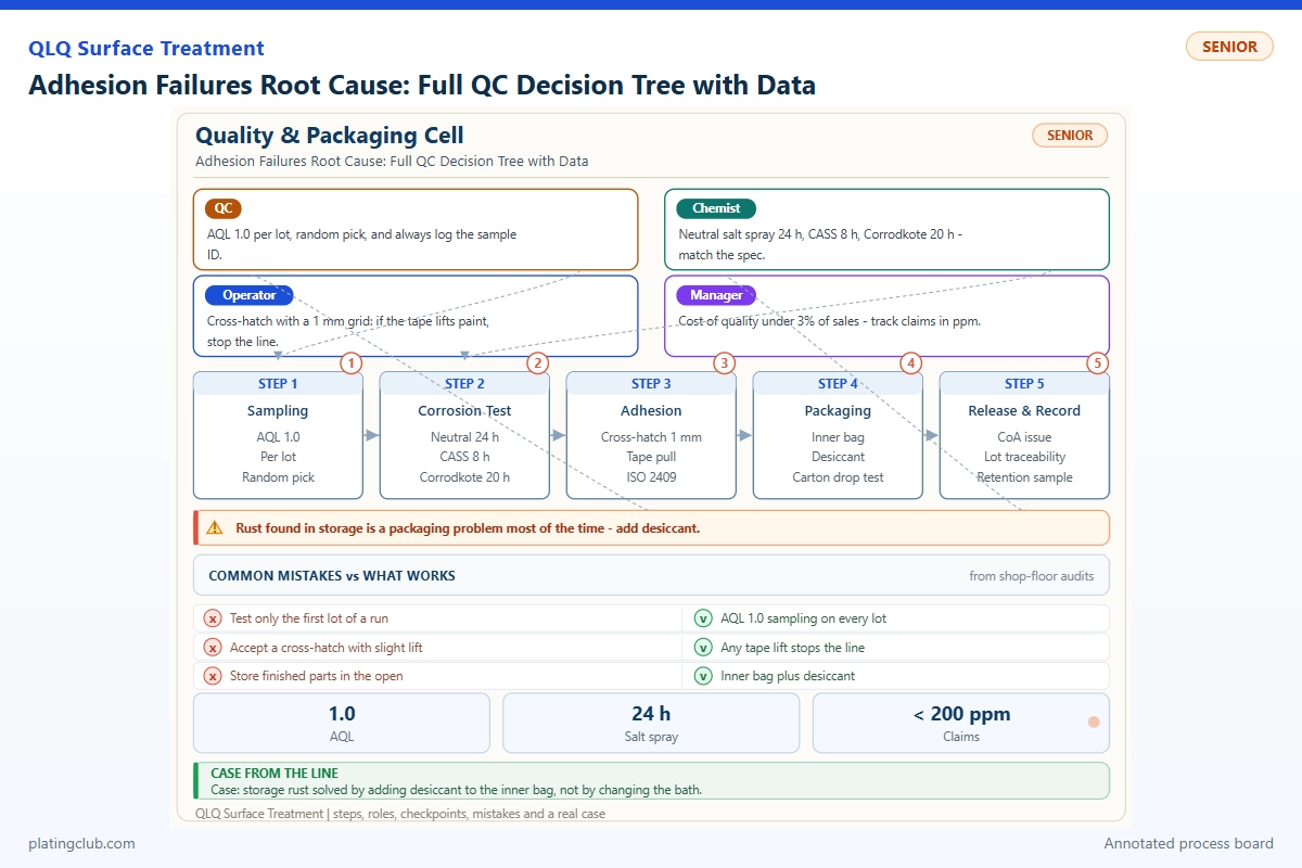
Adhesion Failures Root Cause: Full QC Decision Tree with Data
A management-level investigation must identify the failed interface, isolate the responsible process, and demonstrate that corrective action survives moisture exposure. A harder film, a hotter oven, or a successful tape test alone does not establish root cause.
Scope and Evidence Boundaries
This guide concerns painted zinc-alloy bag hardware and zipper sliders, including primer/topcoat systems and barrel-painted parts. Bare zinc, plated zinc, and previously coated surfaces require separate qualification routes. Never transfer a steel pretreatment recipe to zinc without compatibility testing.
The comparison below contains explicitly illustrative, synthetic experimental data, not QLQ customer results or a laboratory certificate. The complete paint formulation is an engineering starting point, not a validated QLQ product recipe. Numerical control bands are proposed trial limits unless otherwise attributed. Replace them with approved coating technical data sheets, customer specifications, and measured capability before production release.
1. Contain the Lot and Validate the Measurement
Hold material back to the last verified conforming check. Segregate by casting lot, polishing compound, cleaning bath, paint batch, rack or barrel, and oven run. Preserve failed parts, retained paint, and untreated substrates. Photograph defects before stripping; stripping destroys evidence of the failure plane.
First confirm that the test is valid. Use a fresh cutter, controlled tape, documented conditioning, and a trained operator. Record cut spacing, film thickness, tape identification, and removal technique. ASTM D3359 rates adhesion by tape testing; it is not a direct numerical bond-strength measurement. Use the applicable procedure from the licensed standard, rather than treating every cross-cut result as interchangeable. See ASTM D3359.
On small curved sliders, cuts may penetrate unevenly or cross sharp edges. Test matched flat witness coupons alongside actual parts, not instead of them. Verify thickness by a gauge qualified for the substrate and geometry; a conventional magnetic gauge is unsuitable for bare zinc. Use cross-sectional microscopy where instrument readings remain doubtful.
2. Full QC Decision Tree
- Is the failure reproducible with a valid method? If no, correct the measurement system and retest retained samples. If yes, map the failure location and continue. Do not release the lot while method uncertainty remains unresolved.
- Is paint separating from metal? If yes, investigate residual oil, polishing wax, oxide, rinse carryover, conversion-coating compatibility, and post-cleaning handling. Compare a suspect substrate with a separately verified clean substrate using the same paint and cure.
- Does plating detach with the paint? If yes, route the investigation upstream to plating adhesion, activation, and casting condition. Changing paint cannot repair a weak metal-to-metal interface. Preserve flakes for microscopy or elemental analysis.
- Is separation between primer and topcoat? If yes, check recoat time, contamination during storage, primer overbake, incompatible resin systems, and additive migration. Run approved-window versus delayed-recoat coupons with all other conditions fixed.
- Does the film tear internally? If yes, investigate incomplete cure, wrong mix ratio, excessive film build, trapped solvent, or resin imbalance. Profile actual part temperature and compare solvent resistance with a qualified reference film.
- Does failure appear only after water or salt exposure? If yes, check soluble contamination, porosity, edge coverage, and pretreatment integrity. Separate immediate wet testing from recovered testing; recovery can conceal reversible softening.
- Is failure localized to contact points or heavy barrel loads? If yes, examine collision damage, shielding, inaccessible recesses, and uneven drying. Repeat with controlled load and marked witness parts.
- Has one controlled correction removed the failure? If no, test interacting causes with a designed experiment. If yes, repeat across independent runs and worst-case locations before approving restart.
Assign ownership at each branch: QC validates evidence, pretreatment controls cleanliness, painting controls application, maintenance verifies equipment, and management authorizes disposition. An unexplained improvement is not a closed corrective action.
3. Controlled Coupon Comparison
Use one substrate lot and paint batch, three independent coupons per condition, randomized application order, sealed edges, and identical conditioning. The illustrative values below are medians; actual investigations must retain individual readings and photographs. Only one factor changes in each challenge group.
| Group | Test condition | Dry film | Dry tape rating | Water-exposed rating | Pencil hardness | Salt-fog scribe creep |
|---|---|---|---|---|---|---|
| A: Reference | Verified cleaning; 150°C part temperature × 20 min | 24 µm | 5B | 4B | H | 0.8 mm |
| B: Cleaning challenge | Wax-contaminated substrate; same cure as A | 25 µm | 2B | 0B | H | 4.6 mm |
| C: Cure challenge | Verified cleaning; 130°C part temperature × 20 min | 24 µm | 3B | 1B | B | 3.2 mm |
| D: Build challenge | Verified cleaning; same cure as A; excessive build | 48 µm | 3B | 2B | HB | 2.7 mm |
Dry adhesion and scratch pencil hardness are evaluated after 24 hours at 23 ± 2°C. Water-exposed adhesion follows 24 hours in deionized water at 23 ± 2°C, surface blotting, and testing after a fixed 10-minute interval; record this as a specified comparative protocol. Salt-fog exposure is 240 hours using 5% sodium chloride at 35°C under the agreed B117 procedure. Report mean one-sided creep from a substrate-reaching scribe, excluding the original cut width.
Group B illustrates why acceptable hardness cannot clear pretreatment: its film is hard but poorly anchored. Group C suggests cure deficiency; confirmation still requires temperature records and resin-compatible cure tests. Group D flags thickness as a potential contributor, not proof of a universal 48 µm failure threshold.
ASTM D3363 describes pencil hardness, not adhesion. ASTM B117 controls salt-fog exposure; it neither supplies a universal pass criterion nor converts exposure hours into service years. Agree evaluation and acceptance separately.
4. Working Data and Complete Formula Notes
This white waterborne acrylic/melamine trial formula uses industrially plausible proportions. All entries are kilograms as supplied per 100 kg batch. Ranges are experimental adjustment windows, not independently selectable manufacturing tolerances. Water balances the batch to 100 kg; Typical totals exactly 100 kg.
| Component | Range | Typical | Function | Replenishment |
|---|---|---|---|---|
| Hydroxyl acrylic emulsion, approximately 42.5% solids | 52–58 | 55.00 | Film binder | Fresh weighed batch only |
| Compatible highly methylated melamine resin | 8–11 | 10.00 | Crosslinker | No line-side addition |
| Rutile titanium dioxide | 18–22 | 20.00 | White pigment | Qualified grind only |
| Deionized water | Balance | 9.73 | Carrier | Weighed approved correction |
| Ethylene glycol monobutyl ether | 2–3 | 2.50 | Co-solvent | Laboratory-approved correction |
| Aqueous dispersing additive | 0.8–1.2 | 1.00 | Pigment stabilization | Grind-stage dosing |
| Compatible defoamer | 0.1–0.3 | 0.20 | Foam control | Verified microtrial only |
| Dimethylethanolamine | 0.08–0.16 | 0.12 | pH/stability adjustment | Measured laboratory adjustment |
| Compatible sulfonate inhibitor/catalyst package | 0.15–0.35 | 0.25 | Corrosion/cure control | No blind top-up |
| Compatible flash-rust inhibitor | 0.8–1.2 | 1.00 | Package/substrate protection | Fresh batch only |
| Associative polyurethane thickener | 0.1–0.3 | 0.20 | Flow control | Prediluted laboratory adjustment |
| Total | 100 | 100.00 | Complete trial batch | Traceable batch reconciliation |
Prepare the pigment grind, add emulsion under controlled agitation, introduce the compatible melamine premix, then adjust flow. Qualification must establish exact additive grades, dispersion endpoint, stability, flash-off, bake response, and zinc adhesion. This is not a production mixing instruction or a claim that generic substitutes are interchangeable.
The resin family and approximate proportions are informed by BASF's Joncryl 1540 technical sheet, but this table is not its published formulation. BASF identifies amine-related cure retardation and potential intercoat adhesion loss from excessive inhibitor/catalyst addition. Qualify these effects rather than adjusting pH or catalyst to hide a defect. Follow each ingredient's SDS, ventilation requirements, and waste controls.
5. Normal Trends versus Danger Thresholds
These provisional bands apply to the hypothetical trial system, not every paint. Trend by batch and time; intervene before a limit is crossed. A dangerous excursion means hold and investigate, not automatic chemical correction.
| Parameter | Normal fluctuation band | Danger / hold threshold | Diagnostic action |
|---|---|---|---|
| Paint pH at 25°C | 8.2–8.8 | <8.0 or >9.0 | Check calibration, stability and neutralizer history |
| Dry film thickness | 20–28 µm | <15 or >35 µm | Map edges, recesses and cure response |
| Actual part bake temperature | 148–155°C | <145 or >165°C | Profile coldest/heaviest parts |
| Time at qualified cure temperature | 20–25 min | <20 or >30 min | Check residence time and thermal lag |
| Final DI rinse conductivity at 25°C | 5–20 µS/cm | >30 µS/cm | Inspect carryover and rinse renewal |
| Part temperature above dew point | 5–10°C | <3°C | Hold coating; dry and stabilize parts |
| Barrel fill volume | 30–40% | >45% | Reduce load; inspect collision and shielding |
QLQ's local painting note gives a broader 15–30 µm film range and 120–180°C baking range; these are orientation values, not a cure schedule for every resin. The barrel-painting note lists 30–45% loading. The tighter bands above are proposed operating controls. Do not transfer its solvent-paint cup-viscosity figures to this waterborne formula.
6. Two Diagnostic Scenarios and Release Logic
Scenario A: polishing-wax carryover. Sliders fail at recessed areas while flat exposed surfaces appear acceptable. Compare suspect cleaning with verified cleaning on the same casting lot. Inspect recesses and water-break behavior, but do not treat water-break testing as chemical identification. Confirm the failed interface and repeat the corrected cleaning cycle on production geometry. This is a diagnostic scenario, not a documented customer case.
Scenario B: oven loading after capacity expansion. Fully loaded racks fail while lightly loaded racks pass. Instrument heavy and shielded parts, compare time at actual part temperature, and retain identical paint thickness. If loading reduction restores the qualified profile and adhesion, validate the corrected conveyor speed and load limit together. Again, no real customer outcome is asserted.
For restart, require three consecutive independently processed conforming runs as a proposed containment rule, covering normal and worst-case loading. Apply the customer-approved dry and wet adhesion criteria, thickness limits, and corrosion endpoint. QC signs results; engineering signs the mechanism; management approves disposition. Longer corrosion qualification may require continued hold rather than early shipment.
Track first-pass yield, adhesion rejects by interface, rework hours, and recurrence by shift. Never average failing pieces into a passing lot. A stable chart shows control; it does not establish that the selected specification is sufficient.
7. Engineer Notes
- Mark each witness coupon with substrate lot, cleaning batch, paint batch, and oven position before processing.
- Attach thermocouples to representative parts; start cure timing at qualified part temperature, not oven entry.
- Inspect removed flakes under magnification and photograph both sides before assigning the failed interface.
- Test a clean compressed-air discharge on a witness surface; investigate oil and water before connecting air to dried parts.
- Weigh permitted dilution additions and recalculate solids; never replenish a paint tank like a plating bath.
- Retain suspect and approved-reference paint in labeled sealed containers; compare drawdowns before changing suppliers.
- Keep failed coupons, machine settings, and raw readings with the corrective-action record, including unsuccessful trials.
8. Shift Checks
| Shift stage | Check item | Frequency | Acceptance standard | Record |
|---|---|---|---|---|
| Before shift | Gauge, cutter and reference coupon | Every startup | Verified equipment; reference agrees | QC verification sheet |
| Before shift | Paint identity, pH, stability | Each prepared batch | Approved batch; trial pH 8.2–8.8; no coagulation | Batch release sheet |
| Before shift | Cleaning and final rinse | Startup and bath change | Approved cleaning cycle; rinse ≤20 µS/cm | Pretreatment log |
| During shift | Film thickness and recess coverage | First load; hourly; after adjustment | Trial 20–28 µm at mapped locations | Part/coupon measurement map |
| During shift | Thermal profile and load | First run; after load/speed change | Qualified cure profile; approved loading | Logger trace and load record |
| During shift | Adhesion sample collection | Each lot and process excursion | Quarantine pending conditioned test | Sample register and lot status |
| After shift | Raw data and suspect lots | Each handover | No unexplained excursion; holds identified | Signed handover |
| After shift | Conditioned/wet test queue | Daily review | Customer-approved criteria; no overdue release tests | Laboratory queue and disposition |
9. Technician-to-AI FAQ
These are representative troubleshooting prompts, not verified customer quotations.
"AI, our tape test passes dry but fails after water exposure. What should I check first?"
Locate the failed interface, standardize wet-test timing, and compare a verified-clean coupon with the suspect substrate. Check rinse carryover, retained moisture, pretreatment compatibility, and cure. Preserve immediate and recovered results separately. Do not assume that a recovered pass cancels the initial failure.
"AI, the oven shows 150°C, so why is the coating still soft and peeling?"
The display measures an oven condition, not necessarily part temperature. Profile the coldest loaded parts and time above the coating's qualified cure temperature. Then check thickness, mix history, and compatible cure indicators. Raising the setpoint without diagnosis can damage other parts or create intercoat problems.
"AI, can we add hardener or catalyst to stop an adhesion failure today?"
Not without identifying the mechanism and obtaining formulation approval. This one-component baked trial system is not a two-component paint with a freely adjustable hardener ratio. Isolate cleaning, cure, and interface effects first; any authorized modification requires a weighed laboratory trial and requalification.
Source and Qualification Notes
Local QLQ knowledge-base sources: “Painting Process” and “Painting Defect Analysis,” under 02-Product Knowledge / 07-Surface Treatment; “Barrel/Tumbling Spray Painting,” IMA company knowledge-base extract 025. Their original filenames and folder labels are translated here to keep this article English-only. The process notes are draft-status guidance; they do not supply validated adhesion datasets or this paint recipe. External primary sources are linked beside the relevant claims.
Use approved technical sheets, licensed test procedures, and traceable local trials to turn this decision tree into a controlled factory standard. Document any departure before changing production.
What Would You Like to Solve?
Send the substrate route, defect photographs, paint technical sheet, thickness map, cleaning records, and actual part-temperature trace to [email protected]. Identify the failed interface and your required acceptance tests so the discussion starts with evidence. For coordinated process planning, review surface-treatment equipment, chemicals, and engineering support.