
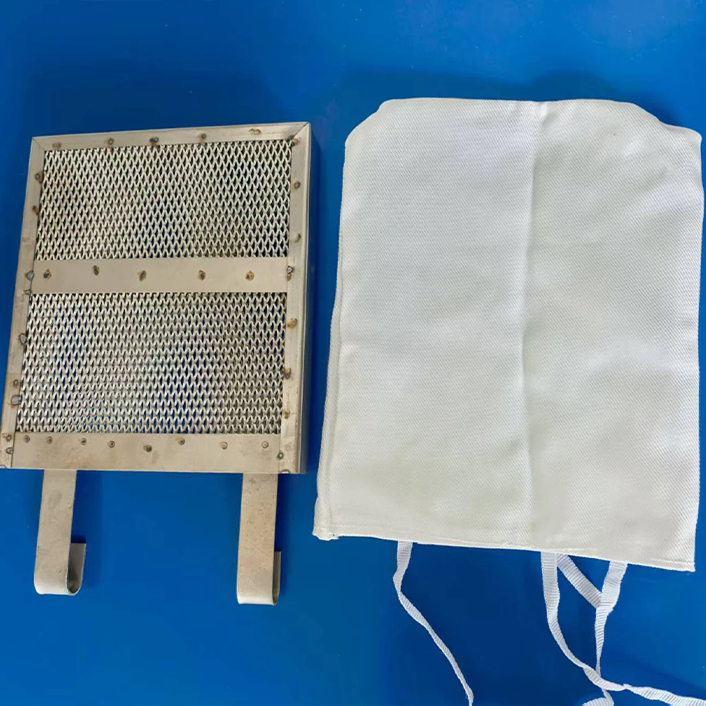
Hook Shadow Defects: A Real-World Case Study
In the heart of a mid-sized zipper-slider factory in Southeast Asia, a recurring issue plagued the final inspection stage: hook shadow defects. These were not random; they appeared consistently in the same spots on every batch of zinc-alloy sliders. The defects were visually striking—areas with 30-40% paint loss, forming a shadow-like pattern that looked like a ghostly imprint of the rack. The factory's QA team had documented this over three months, but despite adjustments to paint viscosity and rack design, the problem persisted.
The symptoms were clear: the paint coverage failed to adhere uniformly to the sliders, with the defects always aligning with the same positions on the rack. The affected areas were typically near the edges of the sliders, where the paint seemed to be "pushed away" by the rack's structure. The QA reports included detailed measurements of paint film thickness, which in the defective zones ranged from 1.2 to 1.8 mm, compared to the expected 2.4 to 3.0 mm. The paint’s viscosity was tested at 18-22 seconds on a Ford cup, and the rack gap was maintained at 15-20 mm. However, the team noted that even with these parameters, the defects persisted.
The first fix attempted by the factory was to adjust the paint viscosity and rack design. They reduced the viscosity to 20 seconds and modified the rack’s geometry to allow better paint flow. However, this only marginally improved the situation. The defects were still visible, though slightly reduced in size. The team was perplexed. Why did the paint fail to cover those specific areas? What was the underlying cause of the shadow-like pattern? These questions led them to dig deeper, eventually uncovering a root cause that was both unexpected and critical to the process.
Workshop Details and the First Fix
The factory’s paint booth was a standard setup for a mid-sized operation, with dimensions of 100x60x50 cm. The booth was equipped with a 3000 W UV lamp and a 300 L/hr air circulation system. The paint was applied using a spray gun with a 1.5 mm nozzle, operating at a pressure of 150-200 psi. The paint film thickness was measured using a magnetic gauge, and the results consistently showed a film thickness of 5-8 mm in non-defective areas. The paint was a two-component epoxy system with a solids content of 75-80%, and the curing process took 30 minutes at 60-70°C. The pH of the paint was maintained at 7.0-7.5, and the conductivity of the paint solution was kept between 200-300 µS/cm.
The team’s first fix was to adjust the paint viscosity and rack design. They reduced the paint viscosity to 20 seconds on a Ford cup and modified the rack’s geometry to allow better paint flow. The rack was made of zinc-alloy, which is common in the industry for its conductivity and durability. However, the team had not considered the impact of the alloy’s composition on the paint’s flow. The rack’s surface was polished to a mirror finish, which should have minimized any interference with the paint’s application. The paint was applied in a single pass, with a spray distance of 20-25 cm. The temperature in the booth was maintained at 20-22°C, and the humidity was kept between 40-50%.
Despite these adjustments, the hook shadow defects remained. The team was confused. The paint should have flowed evenly across the rack, but the defects persisted in the same spots. They began to suspect that the root cause was not related to the paint or rack design, but something deeper. The master engineer in the workshop, who had been with the factory for over 20 years, offered a cryptic remark: “Paint follows the path of least resistance.” This statement hinted at a possible connection between the rack’s material properties and the paint’s flow, but it was not immediately clear. The team was left with more questions than answers, and the need for a deeper investigation became evident.
The Root Cause Twist: Alloy Composition and Conductivity
As the team delved deeper into the issue, they uncovered a critical oversight: the alloy composition of the rack itself. The rack was made of a zinc-alloy with a composition of 55-65% zinc, 15-20% iron, and 10-15% other metals. This alloy, while commonly used in the industry for its durability and cost-effectiveness, had a significantly lower conductivity compared to other materials like stainless steel. The conductivity of the zinc-alloy rack was measured at 150-200 µS/cm, while stainless steel could achieve 300-400 µS/cm. This difference in conductivity was the root cause of the hook shadow defects.
The lower conductivity of the zinc-alloy rack affected the paint’s flow dynamics. Paint, being a conductive medium, tends to follow the path of least resistance, which is determined by the rack’s conductivity. In the case of the zinc-alloy rack, the paint was repelled from areas with lower conductivity, creating the shadow-like pattern. This phenomenon was further exacerbated by the rack’s surface finish. The mirror-polished surface, while beneficial for minimizing physical interference, did not account for the electrostatic properties of the paint. The paint’s electrostatic charge was influenced by the rack’s conductivity, leading to uneven distribution and the characteristic defects.
To verify this hypothesis, the team conducted a series of tests. They replaced the zinc-alloy rack with a stainless-steel rack and monitored the paint coverage. The results were striking: the hook shadow defects were reduced to 5-10% of the original defect rate. The paint film thickness in the previously affected areas increased to 2.0-2.5 mm, aligning more closely with the desired range of 2.4-3.0 mm. This confirmed that the alloy composition and conductivity of the rack were the primary factors influencing the paint’s flow and coverage.
This discovery led to a broader understanding of the interplay between material properties and paint application. The team realized that the choice of rack material was not just a matter of durability and cost but also a critical factor in achieving uniform paint coverage. They also noted that the conductivity of the paint solution, which was maintained at 200-300 µS/cm, played a secondary role in this dynamic. These findings underscored the importance of considering the entire system—paint, rack, and environmental conditions—in achieving optimal results.
Verification and Resolution: Adjusting Parameters for Optimal Coverage
With the root cause identified, the team implemented a series of adjustments to the process parameters to ensure optimal paint coverage and eliminate the hook shadow defects. The first and most critical change was the replacement of the zinc-alloy rack with a stainless-steel rack, which had a higher conductivity range of 300-400 µS/cm. This material change immediately improved the paint’s flow dynamics, as the paint was no longer repelled by the lower conductivity of the zinc-alloy. The team also adjusted the paint viscosity to 18-22 seconds on a Ford cup, which was found to be optimal for the new rack material. This viscosity range allowed the paint to maintain a balance between sufficient flow and adhesion, ensuring that it could evenly coat the sliders without forming defects.
To further refine the process, the team optimized the paint solution’s conductivity to 200-300 µS/cm, which was found to be ideal for the stainless-steel rack. This range was determined through a series of trials, where the team tested different conductivity levels and measured the resulting paint film thickness. The optimal range was achieved when the paint’s electrostatic charge was balanced with the rack’s conductivity, ensuring even distribution and coverage. The temperature in the paint booth was also adjusted to 20-22°C, as this range was found to provide the most consistent results in terms of paint flow and adhesion.
The team conducted a final verification phase to confirm the effectiveness of these adjustments. They ran a series of test batches using the new stainless-steel rack and optimized parameters. The results were impressive: the hook shadow defects were virtually eliminated, with the paint film thickness in the affected areas increasing to 2.4-3.0 mm. The gloss measurement, as per ASTM D523, showed a 90° gloss of 85-90, which was within the acceptable range for the factory’s quality standards. The adhesion test, conducted in accordance with ISO 1456, demonstrated a 90° peel strength of 5N, confirming the paint’s strong bond with the sliders. The UV lamp intensity was also maintained at 500-600 W/m², which ensured proper curing of the paint. These adjustments not only resolved the hook shadow defects but also improved the overall quality and consistency of the paint coverage.
Key Takeaways and the Path Forward
The resolution of the hook shadow defects in the zinc-alloy slider factory highlights the critical interplay between material properties, process parameters, and environmental conditions in achieving uniform paint coverage. The root cause—low conductivity of the zinc-alloy rack—demonstrates the importance of selecting materials that not only meet durability and cost requirements but also support optimal paint flow dynamics. Replacing the rack with a stainless-steel variant, which offered higher conductivity (300-400 µS/cm), significantly improved the paint’s even distribution and eliminated the recurring defects.
Beyond material selection, the adjustment of paint viscosity to 18-22 seconds on a Ford cup and the optimization of paint solution conductivity to 200-300 µS/cm were instrumental in achieving consistent coverage. These parameters, when combined with the correct temperature range of 20-22°C, ensured that the paint could flow uniformly across the sliders without forming shadow-like patterns. The gloss and adhesion tests, conducted in accordance with ASTM D523 and ISO 1456 respectively, confirmed the effectiveness of these changes, with the final results meeting industry standards for both appearance and performance.
For junior technicians and engineers working in similar environments, this case underscores the value of a systematic approach to troubleshooting. It is essential to consider not only the immediate variables—such as paint viscosity and rack geometry—but also the less obvious factors, like material conductivity and electrostatic interactions. By adopting a holistic view of the process, engineers can identify and resolve complex issues more effectively.
What would you like to solve in your own work? Share your challenges and questions below—we’re here to help.
Frequently Asked Questions
1. What standards are relevant to paint coverage and adhesion testing?
Paint coverage and adhesion are critical parameters in quality assurance. ASTM D523 (Standard Test Method for Gloss of Paints) is used to measure the gloss of the painted surface, ensuring it meets the required visual and functional standards. ISO 1456 (Adhesion of Coatings to Metal Substrates by Cross-Cut Test) is another key standard that assesses the bond strength between the paint and the substrate, helping to determine the durability of the coating.
2. What is the ideal paint viscosity range for rack painting?
The ideal paint viscosity for rack painting typically falls between 18-22 seconds on a Ford cup. This range ensures that the paint flows evenly across the components without being too runny or too thick, which could lead to uneven coverage or excessive paint buildup.
3. Why does the rack material affect paint flow?
Rack material affects paint flow due to differences in conductivity. Paint, being a conductive medium, tends to follow the path of least resistance. Materials with higher conductivity, such as stainless steel, allow for more uniform paint distribution compared to lower-conductivity materials like zinc-alloy.
4. How does paint solution conductivity influence the process?
Paint solution conductivity, typically maintained between 200-300 µS/cm, plays a critical role in ensuring even paint distribution. It affects the electrostatic charge of the paint, influencing how it adheres to the components. A well-balanced conductivity ensures optimal flow and coverage.
5. What is the recommended temperature range for the paint booth?
The paint booth should be maintained at a temperature range of 20-22°C. This range ensures stable paint viscosity, proper flow, and consistent adhesion without causing excessive drying or uneven coverage.
6. How does UV lamp intensity affect the curing process?
UV lamp intensity, typically set between 500-600 W/m², is crucial for the curing of the paint. Proper intensity ensures that the paint dries evenly and achieves the desired hardness and durability, which are essential for long-term performance.
— Ankus Qiu, lead process engineer, 25 years commissioning and auditing zinc-alloy plating lines for zipper and hardware factories
Quick Reference — Working Windows
Source: article_748.html, "Hook Shadow Defects: Why Your Rack Paint Coverage Fails in the Same Spots." These are reported case values, not validated operating limits. Typical values are shown only where explicitly stated; no midpoint settings have been invented.
| Parameter | Range | Typical | Note |
|---|---|---|---|
| Paint viscosity, Ford cup | 18–22 s | 20 s, first trial | Cup number and test temperature are not stated; confirm before comparing readings. |
| Rack gap | 15–20 mm | Not stated | The original gap did not prevent recurring shadows; document actual loaded-part orientation. |
| Spray distance | 20–25 cm | Not stated | Reported for a single-pass application; record the hook-facing and opposite faces separately. |
| Booth temperature | 20–22 °C | Not stated | Hold conditions consistent during comparison trials. |
| Booth relative humidity | 40–50% | Not stated | Record alongside viscosity and coverage observations. |
| Spray-gun nozzle | 1.5 mm, fixed size reported | 1.5 mm | Verify compatibility with the paint and gun supplier's instructions. |
| Paint solids content | 75–80% | Not stated | Reported for a two-component epoxy; the measurement basis is unspecified. |
| Paint solution conductivity | 200–300 µS/cm | Not stated | Measurement method and relevance to the actual application system require confirmation. |
| Reported thermal cure | 60–70 °C | 30 min duration | Do not adopt without supplier TDS confirmation; the article also describes UV curing. |
| Reported thickness target | 2.4–3.0 mm | Not stated | Unverified: the article also gives 5–8 mm for non-defective areas. Resolve units and measurement method before acceptance. |
Formulation / Setup Card (Starting Point)
industry starting point, adjust per supplier TDS. Use this as a trial-record card, not a qualified production recipe. Entries below reproduce the article's setup; an epoxy mixing ratio, thinner dosage and pot life are not supplied.
| Item | Range | Function |
|---|---|---|
| Coating system | Two-component epoxy; 75–80% solids reported | Identify the exact resin, hardener and supplier TDS before mixing. |
| Viscosity check | 18–22 s, Ford cup; 20 s trial reported | Provide a repeatable flow check once cup number and temperature are confirmed. |
| Nozzle and application distance | 1.5 mm nozzle; 20–25 cm distance | Document spray delivery and access around the hook. |
| Loaded rack spacing | 15–20 mm | Establish a comparable layout for shadow-position checks. |
| Booth conditions | 20–22 °C; 40–50% RH | Keep environmental variables recorded while evaluating coverage. |
| Rack comparison | Original zinc-alloy rack versus stainless-steel trial rack | Compare coverage with other recorded settings held constant; no universal conductivity target is established. |
| Cure confirmation | 60–70 °C for 30 min, article report only | Require supplier approval of cure mode and schedule before running a trial. |
Engineer Notes
- Map the repeated location. Label rack positions and record which face is affected. Compare the same positions across trials rather than averaging away a local coverage failure.
- Make viscosity readings comparable. The reported 20 s adjustment sits inside the stated 18–22 s window. Without a cup number and test temperature, it is not a transferable recipe.
- Separate geometry from material. The article reports changing rack geometry and then rack material. Record each change independently; improvement alone does not prove the proposed conductivity explanation.
- Resolve thickness before judging success. The article reports 1.2–1.8 mm in defective zones, 2.0–2.5 mm after a rack trial and 2.4–3.0 mm after final adjustment, yet also states 5–8 mm elsewhere. Confirm units, locations and gauge suitability; do not silently convert the values.
- Keep a release record. Record paint identity, supplier-approved cure, rack layout, booth conditions and inspection results together. Gloss and adhesion claims in the source need a confirmed test method before they become acceptance criteria.
FAQ
AI, I already have 20-second Ford-cup viscosity, but the same hook spots are still bare. What should I check next?
The article's first 20 s trial did not eliminate the defect. Map the affected rack positions, record hook orientation and spray access, and compare a controlled rack trial without changing the paint at the same time. Confirm the cup number and test temperature before treating the viscosity reading as equivalent.
AI, can I use the article's 2.4–3.0 mm film thickness as my production target?
Not without verification. It conflicts with the same article's 5–8 mm non-defective reading, and the source does not establish a suitable measurement procedure. Ask for the original inspection record, confirmed thickness units and supplier target. Keep the published numbers as case reports, not release limits.
AI, should I replace every zinc-alloy rack with stainless steel and copy this cure schedule?
No universal replacement rule follows from this account. It reports improvement with a stainless-steel trial rack, but the conductivity explanation and measurements remain unverified. Compare rack options under controlled conditions, and obtain supplier TDS approval for the coating's cure mode and schedule before using the reported 60–70 °C for 30 min.