
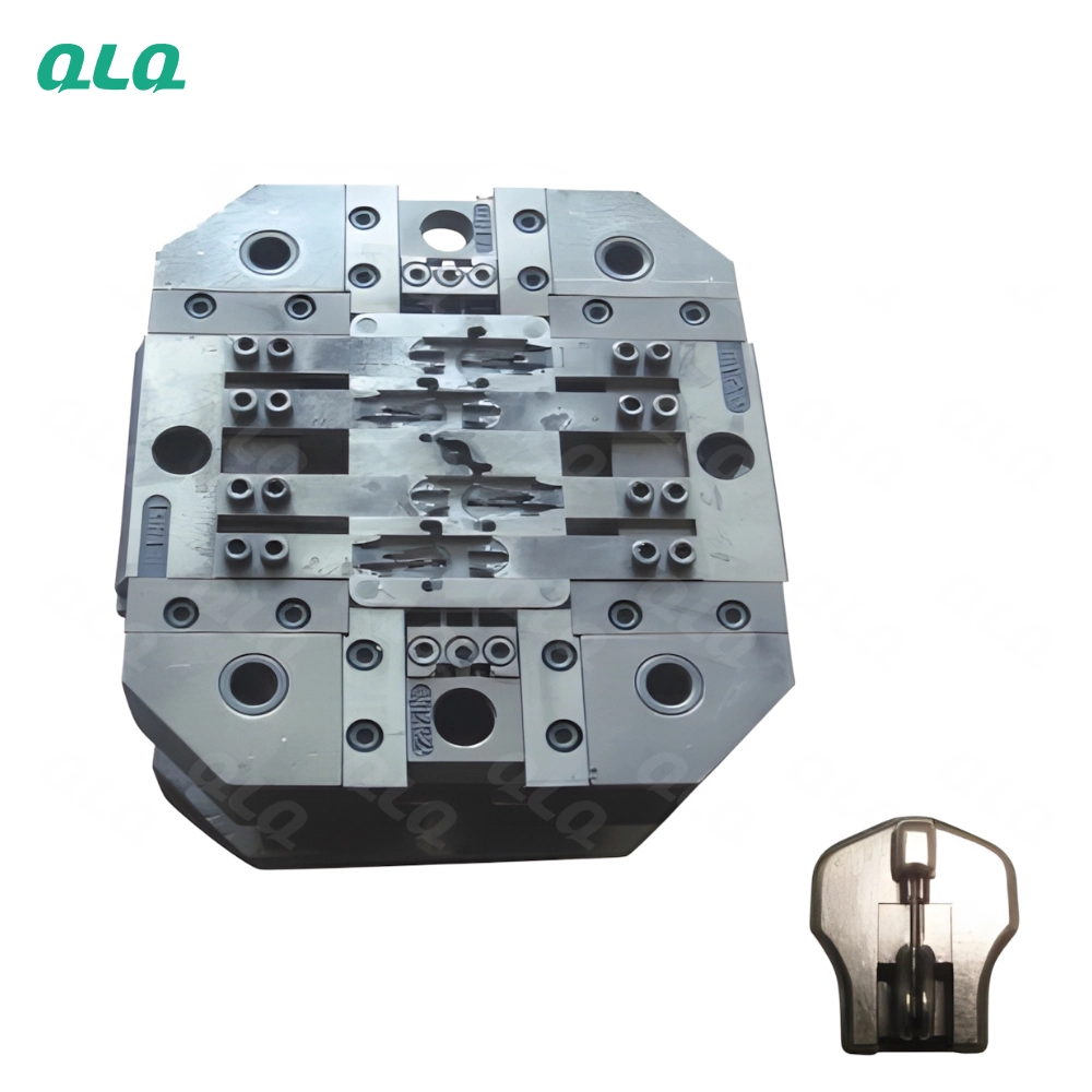
The mould is the most expensive tool on a die-casting line, and every defect that costs money - cold shuts, gas marks, ejector marks, dimensional drift - starts at the parting line, the gate or the cooling channels. Mould care is not maintenance after the fact; it is the set of checks that keep the cavity exactly where the design put it.
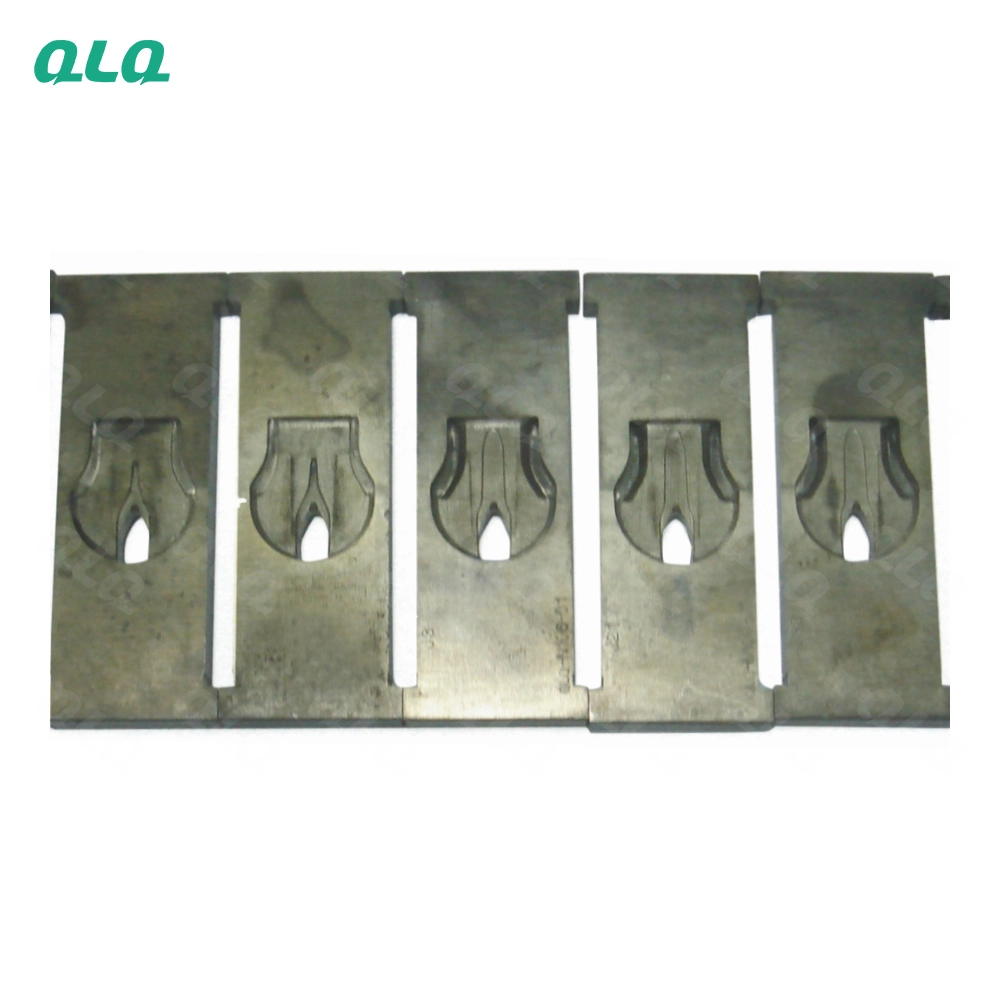
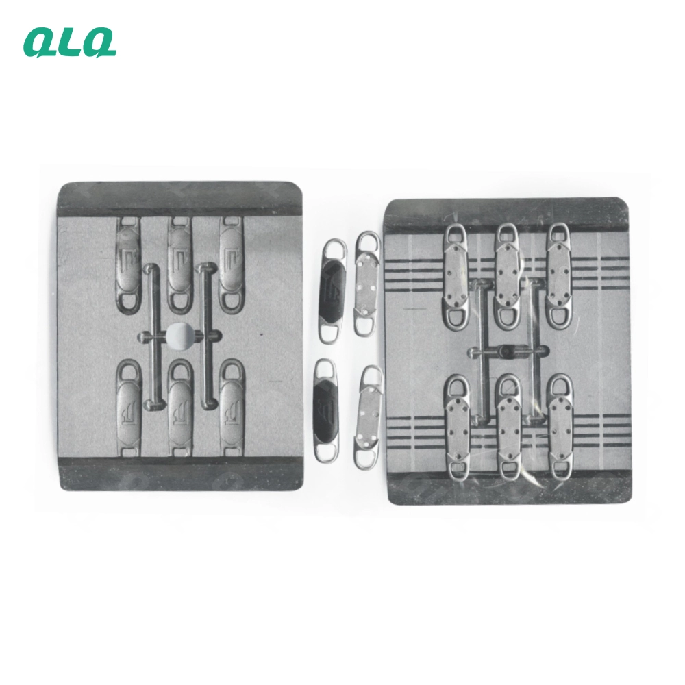
This guide covers the mould-side disciplines QLQ applies with its own 0.02 mm-precision zinc slider moulds: gating and venting checks, cooling circuit verification, surface and hardness care, and the inspection schedule that catches wear before it reaches the customer. QLQ supplies die-casting machines, moulds and finishing lines together, and as China's only full-process manufacturing supplier from raw material through electroplating and painting, mould care is built into the hand-off.
Common Mistakes and How to Avoid Them
The pitfalls that show up most often in real projects, with the cause and the practical fix.
| Mistake | Why It Happens | Practical Fix |
|---|---|---|
| 1. Running the mould dirty | Baked release agent changes fill and part surface | Clean cavities on the maintenance schedule, not on failure |
| 2. Ignoring vent depth | Trapped gas causes burn marks and porosity | Check vent depth and clean blocked vents every run |
| 3. Blocked cooling channels | Hot spots bend parts and drift the cycle | Verify flow per channel; descale on schedule |
| 4. Gate erosion ignored | A worn gate changes fill velocity and flow marks | Measure gate thickness at maintenance and refurbish early |
| 5. Ejector pins dragged | Marks and stuck parts | Check pin clearance and lubrication at each setup |
| 6. Over-polishing the cavity | Chrome edges thin and detail rounds off | Polish with the correct stone and compound only |
| 7. Hardness loss on hot spots | Soft steel wears fast and pits | Check hardness on suspect areas; refurbish or re-nitride |
| 8. Cooling water too hot | Mould cannot hold its window | Hold 15-25 C and check inlet vs outlet |
| 9. No mould log | Wear and fixes are forgotten between runs | Record shots, cleaning, repairs and measurements per mould |
| 10. Storing the mould carelessly | Rust and damage between runs | Clean, protect and store with the mould card |
Best Practices That Hold Up in Production
The operating disciplines that separate a reliable line from a reactive one.
- Clean and inspect the cavity at every scheduled maintenance
- Verify vent depth and clean blocked vents before each run
- Check cooling flow per channel and descale on schedule
- Measure gate thickness at maintenance; refurbish early
- Check ejector pin clearance, lubrication and stroke
- Polish only with approved stones and compounds
- Keep a mould log: shots, cleaning, repairs, measurements
- Protect and store the mould with its card between runs
Implementation Roadmap
A practical sequence that can be adapted to your own project.
Process Flowchart
Mould care flow
A step-by-step sequence with notes and cautions so every shift follows the same order.
- Gate, vent and cooling geometry decide fill quality more than machine settings do.
- Refurbish at the first sign of erosion - waiting multiplies the repair cost.
- Track shots per mould so maintenance is scheduled, not reactive.
- Hot moulds are heavy and burn easily - use lifting gear and gloves.
- Mould cleaning chemicals need ventilation and protection.
- Only qualified toolmakers should weld or re-machine cavities.
Working Data & Formula Notes
Working data - mould geometry and care
Reference values from QLQ zinc-alloy mould practice for sliders and hardware.
| Component / Parameter | Working Value / Role | What Changes Mean (annotation) |
|---|---|---|
| Gate thickness | 0.8-1.2 mm | Sets fill velocity. Too thin blocks and cold-shuts; too thick creates swirl marks and porosity. |
| Runner diameter | 6-10 mm | Feeds the gate with balanced pressure. Wrong sizing starves some cavities in multi-cavity moulds. |
| Cooling channel diameter | 8-12 mm | Carries the heat out. Smaller channels clog sooner; larger need careful spacing. |
| Channel spacing | 30-50 mm, 15-25 mm to cavity | Uniform cooling needs consistent spacing. Tight or uneven spacing bends parts. |
| Cavity hardness | HRC 46-52 | Keeps the cavity dimensionally stable. Soft spots erode and pit quickly. |
| Vent depth | Per design, thin and even | Lets trapped air escape. Too deep flashes; blocked vents burn and porosity. |
| Mould accuracy | +/- 0.02 mm | The precision that keeps parts within finish-class tolerance after plating and painting. |
Reference Data
Specifications and references cited in this guide. Confirm final parameters with your line supplier.
Mould defect to check
| Cold shuts at one location | Gate or vent issue at that section | Measure gate, clean vent |
| Gas burns on edges | Vent blocked or too shallow | Clean and deepen vents per design |
| Part distortion | Uneven cooling | Check channel flow and spacing |
| Flow marks on face | Gate erosion | Measure and refurbish gate |
| Ejector marks | Pin clearance or stroke | Adjust pins |
| Dimensional drift | Cavity wear or soft spot | Measure cavity, check hardness |
Mould maintenance schedule
| Cavity cleaning | Per run or per 5000 shots | Remove release build-up |
| Gate and vent check | Per maintenance | Measure and clean |
| Cooling flow test | Every maintenance | Flow per channel, descale |
| Ejector inspection | Every setup | Clearance, lube, stroke |
| Hardness spot check | Yearly or on wear | HRC 46-52 |
| Full refurbish | On measurement failure | Weld, re-machine, re-nitride |
Implementation Cases
Case 1 - ejector marks that appeared after every repair
Situation. A slider mould kept printing ejector marks after each repair cycle, and the finishing line rejected the faces.
Approach. Pin clearance had been set too tight and pins were dragging. The toolroom adjusted clearance, lubricated the guides and softened the ejector stroke, then logged the setting on the mould card.
Outcome. Ejector marks stopped, and the mould card prevented the same mistake at the next repair.
Case 2 - a silent cooling channel that warped parts
Situation. A buckle line saw intermittent warping in the same corner, blamed on the machine cycle.
Approach. The cooling flow test showed one channel with almost no flow, blocked by scale. The channel was flushed, flow restored, and the cycle stabilised.
Outcome. Warping stopped, and the plant added a flow check per channel to every mould maintenance.
Frequently Asked Questions
Why does mould maintenance matter so much?
The mould defines fill, cooling and part geometry. A worn gate, blocked vent or dead cooling channel produces defects that no machine setting can remove.
How often should I clean the cavity?
Per run or roughly every 5000 shots for zinc sliders, depending on release build-up. Clean on schedule, not when the part starts to fail.
What happens if vents are blocked?
Trapped gas burns the part, creates porosity and raises fill resistance. Check vent depth and clean them at every maintenance.
How do I know a cooling channel is blocked?
Compare flow between channels; a quiet or slow channel is blocked or scaled. Water should be 15-25 C with even flow everywhere.
When should I refurbish the gate?
Measure gate thickness at maintenance and refurbish at the first sign of erosion. A worn gate changes fill velocity and causes flow marks.
Why do ejector marks come back?
Usually pin clearance, lubrication or stroke. Set them correctly and record the values on the mould card so repairs do not repeat the mistake.
What hardness should the cavity be?
HRC 46-52 for H13, SKD61 or 8407 zinc mould steel. Check suspect hot spots; soft areas erode and pit fast.
How do I stop parts sticking?
Check cooling balance and release coating. Sticking is usually a hot mould or worn cavity, not a release-agent problem alone.
How do I track mould condition?
Keep a mould log with shot count, cleaning, measurements, repairs and known issues. Schedule maintenance by shots or calendar.
Does QLQ provide mould support?
QLQ develops zinc slider and hardware moulds to +/- 0.02 mm and supplies them with the die-casting machines, including toolroom guidance for gating, venting and cooling.
What Would You Like to Solve?
If a mould defect keeps returning in the same location, inspect that section: gate, vent, cooling channel and ejector. Share the mould drawing, shot count and the defect photo, and we can help you decide between cleaning, adjustment and refurbishment.
Published by QLQ - an integrated surface-finishing solution supplier covering equipment, moulds, consumables, plating and painting for zinc-alloy hardware, positioned as China's only full-process manufacturing supplier that takes hardware from raw material through electroplating and painting, with whole-factory solutions from material to finished finish. Values cited are project references; confirm with your line supplier before specification.