
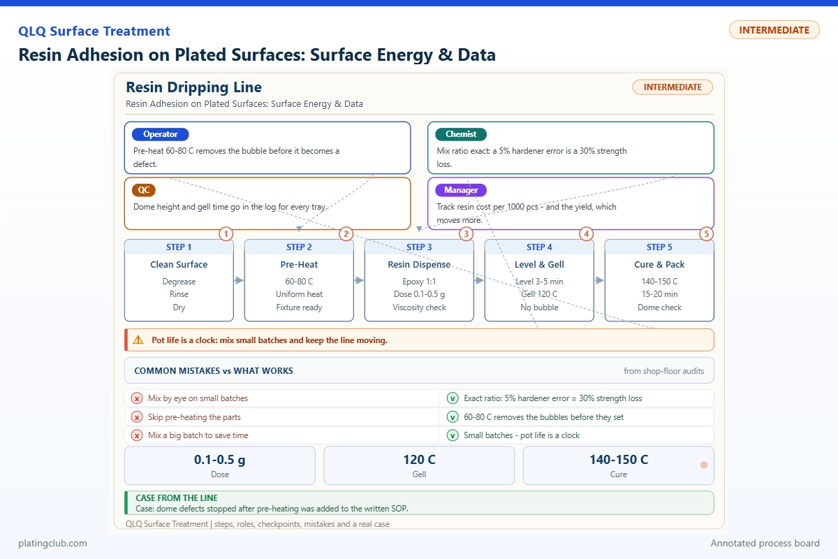
RESIN DRIPPING / SENIOR TECHNICAL PRACTICE
Resin Adhesion on Plated Surfaces: Surface Energy & Data
A clear resin dome can be hard, glossy, and still detach cleanly from a plated recess. Senior technicians must separate wetting, cure, interfacial chemistry, plating integrity, and residual stress. Increasing hardener or extending oven time does not repair every failure.
This guide covers two-component epoxy decoration on plated bag hardware. Silicone dispensing, polyurethane doming, and PVC filling require different chemistry and qualification. Published experiments are identified below; proposed shop limits are commissioning controls, not certified customer results.
1. Identify the failure plane before changing chemistry
Photograph both fracture faces under magnification. If clean metal remains beneath the detached resin, investigate the resin-to-finish interface. Metal flakes attached to resin indicate failure within the plating stack or at the substrate. A fractured, resin-covered surface suggests cohesive failure; tackiness suggests incomplete cure or contamination.
The surface receiving resin may actually be anti-tarnish oil, transparent lacquer, electrophoretic coating, or passivation rather than exposed nickel. Record the complete stack, including every post-plating treatment. QLQ's internal cleaning-and-sealing note identifies oil, wax, polishing residue, and plating-solution residue as cleaning targets, and distinguishes several protective sealing systems. These protections must be treated as separate bonding substrates.
| Observed symptom | First investigation | Controlled response |
|---|---|---|
| Clean lift-off; isolated fisheyes | Sealer, silicone transfer, fingerprints | Compare untouched and approved-cleaned witnesses from one plating lot. |
| Plating transferred to resin | Deposit adhesion, pores, substrate preparation | Contain the plating lot; test an unfilled companion part. |
| Soft center; hard outer edge | Mixing uniformity and thermal history | Check gravimetric ratio and actual part temperature. |
| Hard dome; delayed edge lifting | Stress, moisture ingress, weak boundary layer | Inspect cross-sections and compare aged adhesion, not hardness alone. |
2. Measure wetting without confusing it with bond strength
For an ideal equilibrium surface, Young's relation describes the balance of interfacial tensions. Combining it with the work-of-adhesion relation gives a useful wetting expression:
WA = γL(1 + cos θ)
WA: reversible work of adhesion, mJ/m²; γL: probe-liquid surface tension, mN/m; θ: equilibrium contact angle.
For a hypothetical liquid with γL = 40 mN/m, changing θ from 60° to 30° changes calculated WA from 60 to 74.6 mJ/m². This calculation is not a measured resin bond strength. Roughness, contamination, advancing/receding hysteresis, and cure chemistry prevent direct conversion into a pull-off acceptance value.
One water angle cannot uniquely determine a solid's surface energy. Use a documented multi-liquid method when resolving polar and dispersive contributions. For routine monitoring, a repeatable water-angle test on flat companion coupons is more useful than an unsupported universal dyne target. Use consistent droplet volume, measurement delay, lighting, and coupon orientation; measure five locations and retain the distribution.
Never place dyne ink on saleable bonding surfaces. Curved recesses distort measurements; process flat witnesses alongside actual parts. Also inspect a small drop of the actual mixed resin on a sacrificial part: water wetting and resin spreading are related diagnostics, not interchangeable release tests.
3. Experimental evidence: plated specimens are not interchangeable
Pan and colleagues compared epoxy bonding to electroplated metals on copper packaging covers. The following values are published specimen comparisons, not QLQ production batches. Their application was electronic packaging, not decorative doming. Source: Pan et al., Polymers 2019, Figure 18.
| Specimen | Surface Ra | Delamination area | Resin film thickness | Test condition |
|---|---|---|---|---|
| Cu, lower roughness | 3.2 µm | 2.8% | Not specified for this comparison | LFBGA epoxy/metal bonding; Figure 18 |
| Cu, higher roughness | 3.6 µm | 0% | Not specified for this comparison | Same published comparison |
| Ni, lower roughness | 3.2 µm | 100% | Not specified for this comparison | Same published comparison |
| Ni, higher roughness | 3.6 µm | 60.33% | Not specified for this comparison | Same published comparison |
The paper also reports time-dependent contact-angle changes after plasma treatment. The transferable lesson is to qualify both surface chemistry and treatment-to-bond delay. Its roughness values are not targets for bright decorative hardware; reproducing them could damage appearance or penetrate a thin deposit.
As an independent metal-preparation example, Gougeon Brothers reported copper tensile adhesion of 1,065 psi after 80-grit sanding versus 1,503 psi with additional wet sanding, using PATTI testing. Most reported specimens used 105/205 or 105/206 epoxy and a two-week room-temperature cure. These are comparative metal tests, not permission to sand plated parts. See Effects of Surface Treatment on Epoxy Adhesion to Metals.
Build a local validation dataset
Use matched coupons from at least three plating lots. Compare the current process, approved cleaning, and cleaning plus qualified activation; use five replicates per condition and randomize dispensing order. Keep resin lot, dose, geometry, and cure history constant.
Measure deposit thickness by a validated method and dome height by sectioning or profilometry. Record adhesion mean, minimum, scatter, fracture plane, and hardness on suitable cast witnesses. For corrosion qualification, specify the chosen salt-fog method, exposure duration, scribe status, edge protection, and inspection criteria before testing. Record untested salt-fog performance as “not measured,” never an invented hour rating.
4. Working Data & Formula Notes
A reproducible benchmark is safer than inventing a generic epoxy/amine ratio. The table is a complete as-applied two-component clear mixture using the published WEST SYSTEM 105/207 combination. Its ingredients are proprietary premixes; this is not a disclosure of their raw-material formula, a QLQ product recipe, or a qualified production doming system.
| Component | Range | Typical | Function | Replenishment |
|---|---|---|---|---|
| 105 Epoxy Resin | 100, fixed basis | 100 | Epoxy matrix | Refill its dedicated reservoir; verify metering. |
| 207 Special Clear Hardener | 24.04–29.33 | 27.47 | Crosslinking partner | Refill separately; recheck A:B mass ratio. |
| Added solvent, pigment, filler, silane | 0 for this benchmark | 0 | Excluded to isolate interface effects | No addition or top-up. |
The hardener range is calculated from the supplier's acceptable resin:hardener mass range of 4.16:1 to 3.41:1; the nominal ratio is 3.64:1. A 100 g total batch therefore contains approximately 78.45 g resin and 21.55 g hardener. Its volume ratio is 3:1, not its mass ratio. Source: 105 System technical data sheets, 105/207 page.
The same sheet reports mixed viscosity of 760 mPa·s at 72°F, 100 g pot life of 22–26 minutes, and Shore D hardness of 84.4. These are supplier reference properties, not measurements on a plated dome. Thin-film working time must not be substituted for cup pot life.
Do not replenish mixed material or dilute a thickening batch. Make a fresh weighed batch. Changing supplier, hardener, pigment loading, or reactive diluent requires renewed qualification; mass ratios are not transferable across resin systems. Follow current supplier instructions, maximum casting depth, SDS, and exotherm controls.
5. Trend bands and danger thresholds
The following are proposed commissioning bands for the benchmark trial, not universal material limits. Validate them against aged adhesion before approving a control plan. Supplier safety and processing limits override these proposals. Values outside the normal band require investigation; a danger threshold means stop and segregate.
| Parameter | Normal fluctuation band | Danger threshold | Interpretation and action |
|---|---|---|---|
| Water contact angle | 20–40° on qualified witnesses | >60° or >15° above qualified baseline | Suspect contamination or activation aging; repeat clean/activation validation. |
| Resin:hardener mass ratio | 3.57–3.71:1, proposed tight band | Outside supplier range 3.41–4.16:1 | Quarantine since last valid metering check. |
| Material temperature | 21–25°C | <16°C; >30°C triggers hold | Cold cure or shortened open time; recondition before mixing. |
| Part temperature above dew point | 5–10°C margin | <3°C margin | Hold to prevent condensation; investigate excessive heating too. |
| Activation-to-dispense delay | 0–30 minutes in protected storage | >60 minutes | Recheck wetting; extend only with aging evidence. |
| Mixed-batch age at approximately 22°C | 0–10 minutes, maximum 100 g trial batch | >15 minutes or visible self-heating | Discard safely; never rescue with solvent. |
| Dispensed mass | 95–105% of qualified target | <90% or >110% | Inspect starvation, overflow, dome height, and shrinkage stress. |
| Final-rinse conductivity | 0–20 µS/cm at temperature-compensated reference | >50 µS/cm | Investigate drag-in and refresh rinse; conductivity does not detect all oils. |
Plot these variables by plating lot, operator, resin lot, and elapsed time. A steady angle increase within the nominal band can justify action before a limit is crossed. Keep specification limits distinct from statistical control limits calculated from a stable process.
6. Two diagnostic cases to apply on the line
Case A: nickel-finished recesses fail despite normal hardness
This is a diagnostic scenario, not a claimed customer outcome. Split one incoming lot before and after its sealing operation. Prepare matched resin witnesses without changing cure. If only sealed pieces fail, investigate sealer compatibility; if both fail, examine contamination, plating integrity, and activation. Do not remove the entire corrosion-protection system without validating the revised exposed areas.
Case B: afternoon batches lift after storage
This is also a diagnostic scenario. Compare freshly activated coupons with coupons held 30, 60, and 120 minutes under actual shop conditions. Repeat across different plating lots while logging contact angle and aged adhesion. If wetting and adhesion deteriorate with delay, shorten the queue and protect staging trays. If wetting stays stable, examine cure history, dose growth, moisture exposure, and mixed-batch aging instead.
7. Engineer Notes
- Tag every witness with substrate, plating stack, sealer, treatment time, resin lot, and cure position. Keep failed parts and fracture photographs together.
- Weigh separate resin and hardener delivery shots after reservoir refills. Verify ratio over several shots; a single combined shot cannot reveal component imbalance.
- Scrape the mixing vessel sides and bottom, transfer to a clean vessel, and remix using the supplier-approved procedure. Keep the batch shallow and within its mass limit.
- Validate vacuum degassing with the chosen material. Avoid boiling volatile constituents or allowing degassing to consume the usable dispensing window.
- Map activation across the full recess, not only a flat exposed face. Confirm treatment coverage and monitor discoloration or coating damage on sacrificial parts.
- Place a thermocouple on representative hardware during cure. Record part temperature and dwell, not merely oven setpoint; do not improvise a higher-temperature cure.
- Inspect aged specimens immediately after exposure and after a defined recovery period. Separate wet interfacial failure from permanent plating damage.
8. Shift Checks
| Shift stage | Check item | Frequency | Acceptance standard | Record |
|---|---|---|---|---|
| Before shift | Incoming finish and witnesses | Every plating lot | Approved stack; no unauthorized sealer change | Traveler and finish revision |
| Before shift | Metering, temperature, dew-point margin | Startup and refill | Normal bands above; calibrated balance | Separate shot weights and temperatures |
| During shift | Contact angle and staging delay | Hourly and after activation changes | Qualified wetting band; delay no more than 30 minutes | Five readings and timestamps |
| During shift | Batch age and dose mass | Every mix; dose every 30 minutes | No self-heating; age and dose within normal bands | Mix ID, start time, shot mass |
| During shift | Rinse and cure profile | Hourly; each cure load | Approved rinse band and validated part-temperature profile | Conductivity and temperature trace |
| After shift | Witness cure and delayed adhesion | Every shift's retained set | Approved hardness baseline and qualified adhesion minimum | Test date, cure age, failure plane |
| After shift | Material reconciliation and containment | Shift closure | Traceable lots; all excursions segregated | Hold quantities and disposition owner |
9. FAQ: technician-to-AI questions
These direct-question prompts are editorial examples, not quotations from recorded customer conversations.
“AI, the resin is hard but peels off our nickel-plated parts. Should I add more hardener?”
No. Verify ratio and cure, then inspect the fracture plane. Normal hardness cannot prove interfacial adhesion. Extra hardener can create another defect. Compare sealed and unsealed witnesses and investigate surface contamination before changing the material.
“AI, our dyne reading passes. Why do the domes still fail after aging?”
A wetting check does not measure plating adhesion, cure stress, or moisture resistance. Test matched aged coupons, inspect both fracture faces, and verify that the measured surface is the actual bonding layer. Do not release a batch solely from a dyne reading.
“AI, can we copy the published roughness and plasma settings onto bright chrome hardware?”
Not directly. Different deposit thicknesses, sealers, recess geometries, and activation equipment change the result. Run sacrificial trials and confirm appearance, corrosion performance, and aged adhesion before adopting any setting.
10. What Would You Like to Solve?
Send the plating stack, resin technical sheet, fracture photographs, dose, cure trace, and aging conditions to [email protected]. For coordinated process planning, see surface-treatment lines, equipment, chemicals, and support. The useful next step is a controlled comparison, not a promised universal adhesion value.
Internal grounding: QLQ Obsidian Vault, cleaning-and-sealing note in the surface-treatment process folder, and slider plating-and-painting note in the slider-process folder. These notes support cleaning and finish-stack context only. Resin-specific QLQ trial reports are unavailable and require confirmation. Published data and the benchmark formulation are attributed inline; commissioning bands and diagnostic scenarios require local validation.