
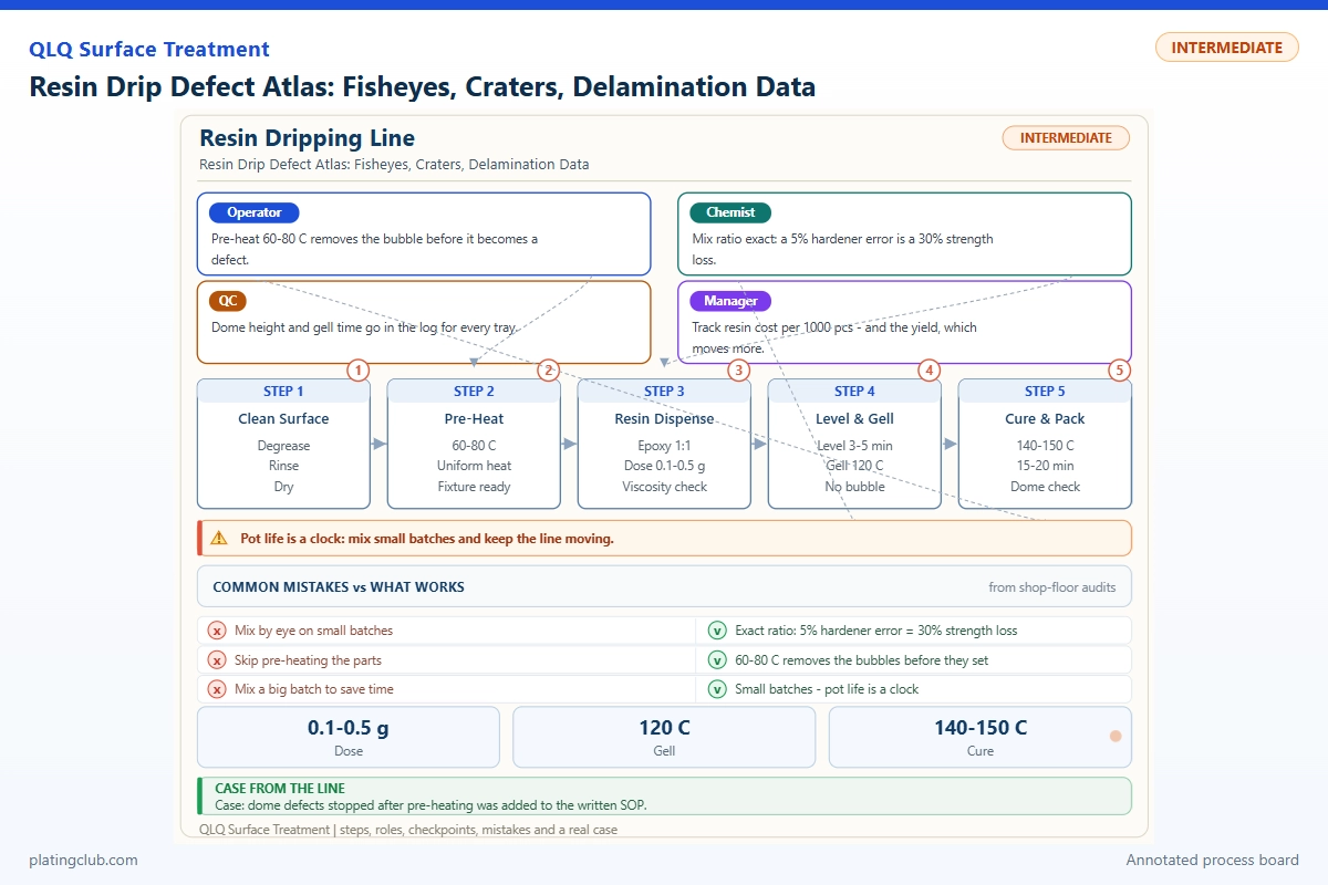
Resin dripping / Junior technician / Defect diagnosis
Resin Drip Defect Atlas: Fisheyes, Craters, Delamination Data
A circular hole in a wet resin dome, a depression after curing, and a lifted edge require different investigations. This atlas helps technicians with three or more years of finishing experience separate appearance defects from adhesion failures on plated zinc-alloy bag hardware, decorative badges, and recessed metal emblems.
Scope: two-component epoxy doming. Silicone, PVC, polyurethane, and UV-curing materials require separate work instructions. Identify the chemistry before changing settings.
Evidence first: what these numbers mean
Supplier reference properties below are published values, not QLQ production results. The coupon matrix is an executable experiment with unmeasured fields clearly identified. No verified customer batch report, salt-spray result, or resin formulation was available in the searched QLQ knowledge-base notes; those results remain pending confirmation.
Local source: QLQ Obsidian Vault, equipment catalogue, page 25, stored under 03-equipment-technology/company-directory/machine-directory/page-25 as an English locator. That note lists QLQ-LSVM for liquid silicone vacuum processing and QLQ-12LSDM for silicone dispensing. Neither listing establishes epoxy compatibility. Confirm wetted materials, seals, metering, and cleaning requirements before equipment selection.
All proposed control bands in this article are trial work-instruction limits, not universal chemistry thresholds. A supervisor must approve them against the current resin technical data sheet, substrate specification, and customer acceptance criteria.
Defect atlas: inspect shape, timing, and interface
| Defect | Recognition | First comparison | Containment and next action |
|---|---|---|---|
| Fisheye | A wet film retreats around a centre; the substrate may remain exposed. | Compare approved-clean and production-prepared coupons using one resin mix. | Hold the affected tray. Investigate handling, polishing residue, release agents, cups, and wipes before changing resin. |
| Crater | A shallow depression appears during levelling or cure; a bubble or particle may occupy its centre. | Photograph immediately after dispensing and again before gel. Track whether a bubble collapses at that location. | Inspect mixing, nozzle purging, dust protection, and substrate condition. A round depression alone does not prove contamination. |
| Delamination | Edges whiten, blister, or separate; a lifted fragment reveals an interface. | Inspect both fracture faces under magnification: resin-to-topcoat, topcoat-to-plating, or plating-to-metal. | Quarantine the lot and preserve failed pieces. A resin adjustment cannot repair plating that separates from zinc. |
Record the first appearance time, tray position, cavity number, upstream finish, and mixing batch. A row-dependent pattern suggests something different from randomly scattered defects. Preserve one untouched failed part: wiping every sample destroys evidence.
WEST SYSTEM connects epoxy fisheyes with contaminated or inadequately prepared surfaces. Its troubleshooting advice also identifies contaminated mixing equipment and silicone-bearing cloths as possible sources. Use these as investigation leads, not proof that every crater is silicone-related. Source: WEST SYSTEM epoxy troubleshooting.
Working Data & Formula Notes
A complete shop-floor recipe can consist of two preformulated components. It need not reveal the supplier's proprietary raw ingredients. Feroca's rigid ClearWater doming system specifies 100 parts A to 30 parts B by weight. The table accounts for the entire unpigmented mix; it is not a QLQ proprietary formulation or approval for a particular plated finish. Source: Feroca rigid doming specifications.
| Component | Range | Typical | Function | Replenishment |
|---|---|---|---|---|
| Matched component A, formulated epoxy base | 100 parts reference; fixed recipe basis | 100.0 g; 76.923% of final mix | Provides the formulated resin phase and optical properties. | Refill only the separate A reservoir with the approved grade and logged lot. |
| Matched component B, curing component | 30 parts nominal; proposed weighing-control band 29.7–30.3 per 100 A | 30.0 g; 23.077% of final mix | Reacts with A to form the cured network. | Refill only the separate B reservoir. Check metering after refill; do not correct an ageing mixed cup. |
The narrow weighing band is a proposed equipment-control tolerance, not supplier permission to vary stoichiometry. No solvent, water, pigment, defoamer, or adhesion additive belongs in this baseline recipe. Any approved additive creates a new controlled recipe and requires requalification.
Calculate hardener mass as mB = mA × 0.30. Thus 80.0 g A requires 24.0 g B, giving 104.0 g total. Record actual masses, not only the target. For a 0.1 g balance, avoid tiny batches whose hardener quantity approaches the instrument's practical uncertainty.
This is reactive batch preparation, not plating-bath replenishment. Never extend pot life by topping up old mixed resin. Label the cup when A and B first contact, and follow the approved waste procedure for expired material.
Reference properties and a controlled coupon experiment
| System | A:B by mass | Working life | Cure reference | Hardness | Test condition |
|---|---|---|---|---|---|
| Feroca ClearWater rigid doming | 100:30 | 15 minutes | 24 hours; allow 48–72 hours for full mechanical cure | Shore D 80, supplier value | Working life at 20–22°C; room-temperature processing. Hardness test method not specified on the product page. |
| Epoxyset EB-107LP-1 | 100:25 | 2 hours | 3 hours at 65°C; alternate 24–48 hours at 25°C | Shore D 85, supplier value | Pot life: 100 g at 25°C. Hardness conditioning not specified on the product page. |
Epoxyset also publishes mixed viscosity of 100–200 mPa·s and identifies small-component doming as an application. These figures demonstrate why a generic “epoxy setting” is unreliable. They do not predict adhesion or salt-spray performance on your hardware. Source: Epoxyset EB-107LP-1 data.
For the experiment, prepare three coupons per group from one plated lot and use one freshly mixed resin batch. Randomise tray positions. The challenged conditions stay in a segregated laboratory trial, never saleable production. Keep retained coupons for repeat testing.
| Group | Controlled difference | Film thickness | Hardness / adhesion | Salt-spray record | Test condition |
|---|---|---|---|---|---|
| A: reference | Approved cleaning and preparation | Target 0.60 ± 0.10 mm; measured value pending | Companion hardness specimen and interface result pending | Not tested | Three coupons; proposed 23 ± 2°C; identical cure and dispensing geometry |
| B: handling comparison | Current production handling instead of reference handling | Same target; measured value pending | Results pending | Not tested | Three coupons; all other conditions match A; photograph wetting at fixed intervals |
| C: dispensing comparison | Current production nozzle instead of verified-clean trial nozzle | Same target; measured value pending | Results pending | Not tested | Three coupons; all other conditions match A; record nozzle identity and purge history |
Measure thickness by an approved method suitable for the metal/resin stack, or use a sacrificial cross-section. A magnetic gauge may not isolate the resin layer on plated zinc. Report centre and edge locations separately rather than hiding dome geometry in one average.
Do not take a Shore D reading directly through a thin dome onto metal and compare it with a bulk-resin specification. Prepare a suitable companion specimen using the selected hardness method's geometry. Photograph the adhesion failure plane; use the customer's approved method for the actual coating thickness.
If salt spray is required, agree the method, exposure duration, edge sealing, scribing, and acceptance criteria beforehand. Record blistering, corrosion location, and delamination separately. “Not tested” must never become an invented pass or a promised service life.
Trend bands: distinguish normal variation from a hold trigger
The following provisional controls apply to the 100:30 reference trial. Validate them before production. A hold trigger means investigate and obtain disposition; it is not a scientifically established failure boundary. pH is not a useful direct control for this solvent-free epoxy mixture.
| Parameter | Proposed normal band | Danger / hold threshold | Technician response |
|---|---|---|---|
| B mass per 100 A | 29.7–30.3 g, target 30.0 | Outside the approved tolerance | Hold mix; verify tare, balance, and pump output. |
| Workstation temperature | 20–25°C | Below 18°C or above 30°C | Pause the trial and reassess cure or shortened working time. |
| Relative humidity | 40–60%, proposed trial band | Above 70% or observed condensation | Check substrate dryness and environmental control. |
| Surface temperature above dew point | At least 3°C margin | Below 3°C margin | Hold parts until dry and equilibrated; log both temperatures. |
| Mixed-material age | 0–10 minutes, conservative trial window | 10 minutes: internal hold; 15 minutes: published pot-life reference at 20–22°C | Discard according to approved instructions; never assume a warm cup has the reference life. |
| Dome centre thickness | 0.50–0.70 mm for the trial geometry | Outside drawing tolerance | Hold tray and check dose, cavity area, and fixture level. |
| Dispensed shot mass | Approved target ±5%, provisional | More than ±10%, or drawing limit exceeded | Recheck ten shots by mass; replace blocked or damaged dispensing hardware. |
Plot readings against mixing time and tray sequence. A gradual change within the band can still matter: increasing shot mass with unchanged programming may precede overflow. Keep the numerical history so the next shift can identify drift.
Engineer Notes
- Number rejected parts before cleaning them. Photograph with a scale marker under identical lighting, and separate wet-film defects from post-cure failures.
- Check surface preparation on sacrificial coupons. WEST SYSTEM describes water sheeting as a useful contamination screen, but notes that water-soluble residues can escape detection. Dry completely afterwards. Source: WEST SYSTEM surface preparation.
- Approve any abrasion on plated hardware through the finish owner. Generic coarse-sanding advice must not be applied blindly to decorative plating or thin protective topcoats.
- Verify the two pumps separately by collecting and weighing their outputs. Combined shot weight alone cannot show that the A:B ratio is correct.
- Put the mixing timer beside the dispenser. Count mixing, transfer, any approved degassing, and application within the working window; do not restart the timer after transfer.
- Keep a retained resin specimen for each investigated batch. Label material lots, actual ratio, cure history, and inspection date so hardness changes remain traceable.
- Use SDS-specified gloves, eye protection, ventilation, and spill controls. Do not use an open flame near finishing solvents. Restrict heating and vacuum treatment to qualified instructions.
Two diagnostic cases to practise
These are training scenarios, not documented customer successes or measured outcomes.
Case 1: fisheyes on recessed bag emblems
Defects cluster on one tray after a handling change. Compare reference-prepared coupons with coupons following the actual production route. Keep resin, thickness, and cure unchanged. If only the production-route group fails, trace that route one step at a time. If both fail, investigate shared material and equipment. The junior technician's deliverable is a labelled comparison, not a guess about silicone.
Case 2: edge lifting on plated zipper pull decorations
Parts appear sound at first inspection but lift during an approved conditioning test. Preserve fragments and identify the separation plane. Compare retained parts from the same plating lot, including undecorated parts where available. If plating is attached to the resin fragment, involve the upstream plating team. If separation occurs above a clear topcoat, evaluate that interface through the finish owner. Close the investigation only after the selected correction survives repeat qualification.
Shift Checks
| Shift stage | Check item | Frequency | Acceptance standard | Record |
|---|---|---|---|---|
| Before shift | Material identity and balance | Start; every material change | Matched approved A/B lots; balance passes its documented check | Lot codes, expiry, check weight, operator |
| Before shift | Environment and first-piece approval | Start; after interruption | Approved bands; dry substrate; conforming reference piece | Temperature, humidity, dew-point margin, photograph |
| During shift | Ratio and mixed age | Every mix; pump check after refill | Approved ratio; application finishes inside validated working window | Actual masses, mix start, last dispensing time |
| During shift | Shot mass and defects | Ten shots at setup; hourly and after nozzle change | Approved dose; no customer-prohibited defects | Individual weights, inspected quantity, rejects by type |
| After shift | Cure identification and retained samples | Every retained batch | Trays traceable; full required cure completed before release | Tray IDs, cure start/end, retained specimen location |
| After shift | Cleaning and handover | Shift end | Approved cleaning completed; held lots clearly segregated | Cleaning sign-off, waste record, open issues and owner |
FAQ: technician questions to AI
“AI, my resin has round holes. Should I add more hardener?”
No. Preserve the specified ratio. First establish whether the film retreats while wet or a bubble collapses later. Compare controlled coupons and check preparation and dispensing. More hardener is not a validated crater remedy.
“AI, the dome feels hard, so why does it peel off the plating?”
Hardness and adhesion measure different things. Identify the failure plane and inspect the finish beneath it. A hard resin can separate from an incompatible topcoat, while poorly attached plating can detach beneath otherwise sound resin.
“AI, can I report a salt-spray pass before the lab finishes?”
No. Report the test as pending, including the agreed method and specimen IDs. Published resin hardness does not establish corrosion resistance for the complete plated-and-domed component. Release requires authorised evidence.
What Would You Like to Solve?
Send defect photographs, substrate and plating stack, resin identity, actual A:B weights, cure history, and the acceptance test you need to meet to [email protected]. These records support a focused engineering review. For upstream process coordination, see surface-treatment line equipment, chemistry, and support.